YG300_Ope_E.pdf - 第31页
1-3 1 Part names and functions n C o n n e c t i o n b e t w e e n m a c h i n e s ( i n p u t / o u t p u t s i g n a l s b e t w e e n m a c h i n e s ) T h e i n t e r f a c e c o n n e c t o r l a b e l e d " P …
1-2
1
Part names and functions
n
Signal light
Indicates current operating conditions of the mounter with a green, yellow and red light explained below.
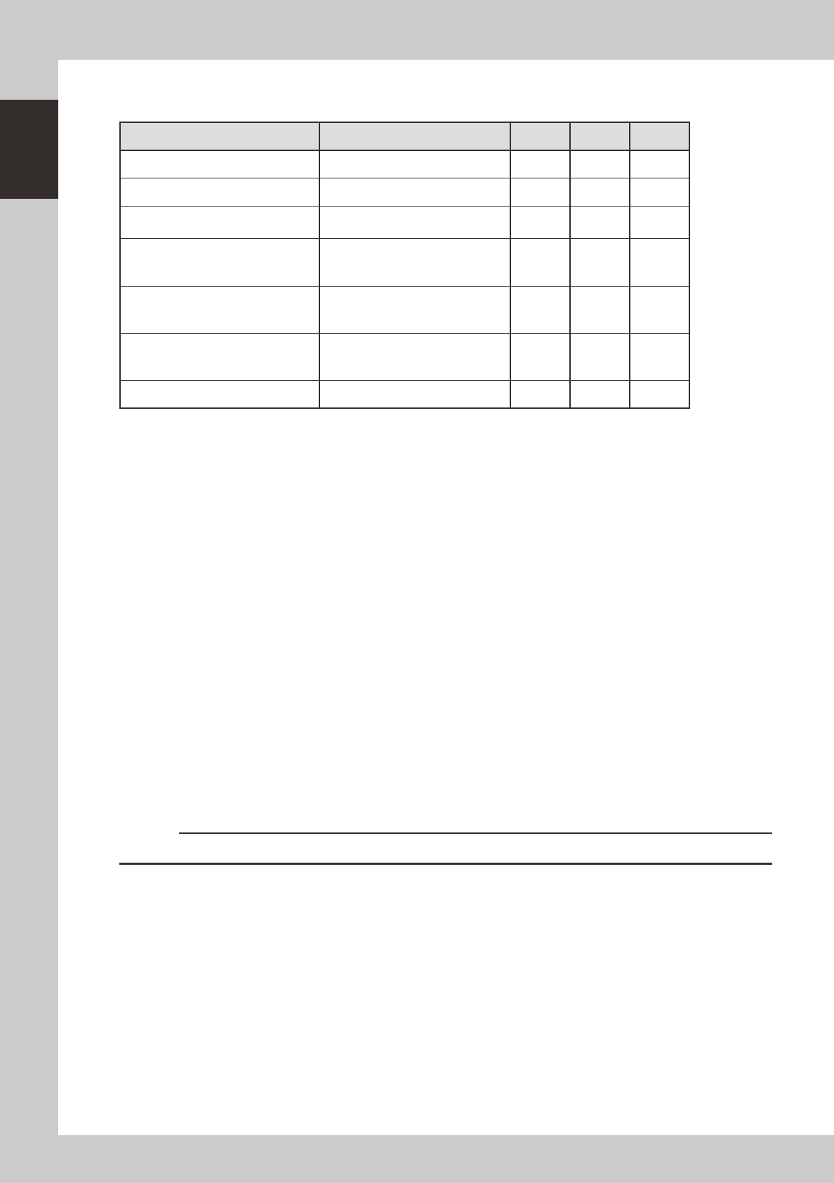
Machine status Example Green Red Yellow
Warm-up or automatic operation ON ----- -----
Emergency stop ----- ON -----
System error
(with buzzer ON)
• Excessive current
• Secondary limit over
----- ON -----
Particular part placement table
stopped due to error
(with buzzer ON)
• Pickup error, recognition error, etc. ON ----- Flashing
Entire machine stopped due to error
Board data check error, etc
(with buzzer ON)
• Board transfer error, data check
error, etc.
----- ----- ON
Components cannot be used.
• Components run out.
Tray changer door is opened.
• Non-stop exchange carriage is off.
----- ----- Flashing
Dump station is full. (When the option is installed) ----- ----- Flashing
n
Alarm buzzer
This buzzer sounds if an error or abnormal operation occurs. (Volume can be adjusted by turning the buzzer ring right or
left.)
n
Safety cover
This cover must be closed during operation. If opened, emergency stop is triggered.
n
Pressure gauge
Shows the supply air pressure (upper display) and pressure-drop detection level (lower display).
A normal pressure value is shown in green, and an abnormal pressure value in red.
Use the pressure regulator knob and the arrow buttons on the pressure gauge to set each pressure value as follows:
• Supply air pressure (upper display) : 0.55 MPa
• Pressure-drop detection level (lower display) : 0.45 MPa
n
Head assembly
Picks up and mounts components with the nozzles at the tip. Also has a camera for recognizing marks on board. (See "3.
Head assembly" in this chapter.)
n
Front panel
Installed behind this panel are the system mother board, power supply board, servo control board, vision board and
CD-ROM drive.Keep this panel closed during operation.
n
Power switch
Turns on or off the power to the machine. The power is on when turned to the right.
c
CAUTION
Wait about 2 seconds before turning the power switch back on after turning it off.
1-3
1
Part names and functions
n
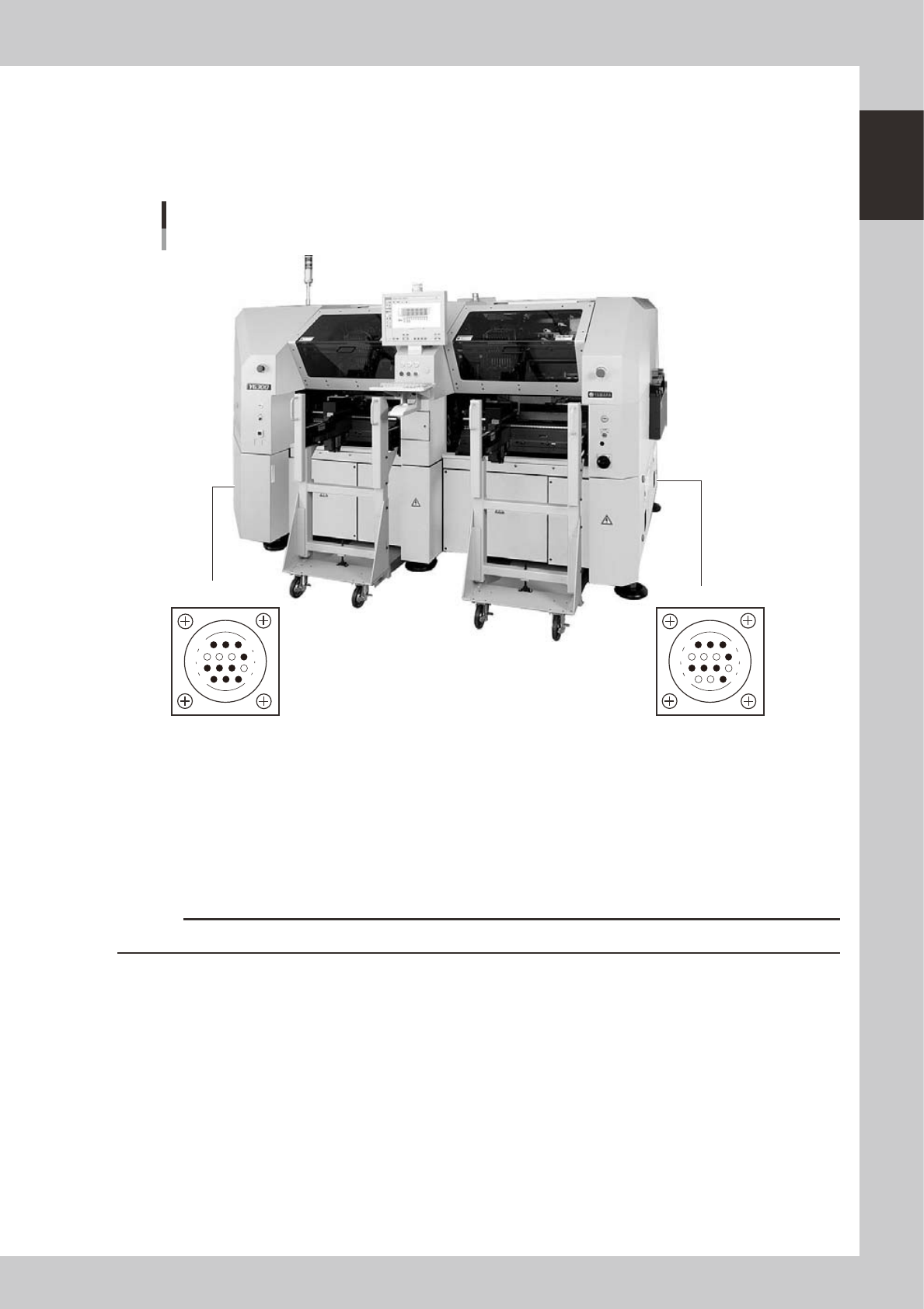
Connection between machines (input/output signals between machines)
The interface connector labeled "PREVIOUS INTERFACE" connects to the machine in the preceding process, and the
interface connector labeled "NEXT INTERFACE" connects to the machine in the next process.
In the case of standard machines of right-to-left flow, the PREVIOUS INTERFACE connector is located on the right side of
the machine, and the NEXT INTERFACE connector on the left side.
PREVIOUS INTERFACENEXT INTERFACE
Connector : AMP 206043-1 (14-pin receptacle)
Machine-to-machine interface connectors
Right-to-left flow
14
11
12
7
4
8
3
1
14
11
12
7
4
8
1
3
23101-M3-00
There are two methods for machine-to-machine connection: "ADVANCE GATE" and "GATE IN/OUT". The connection
method differs according to the machine to be connected.
• ADVANCE GATE
Use this method when connecting this machine to YAMAHA surface mounter "X series" or later models.
• GATE IN/OUT"
Use this method when connecting this machine to YAMAHA surface mounter "II series" or earlier models, or other
manufacturers' machines.
c
CAUTION
If connecting to a machine or equipment other than above, please consult us.
n
Feeder setup section
Mainly tape feeders are installed here. (See "4.1 Supplying components from feeder plates" for details.
1-4
1
Part names and functions
2. Operation panel and data input unit
Standard machines are equipped with an operation display, operation panel buttons, a keyboard and a
trackball on the front and rear of the machine, to operate the machine and make data settings. The functions
of these units are explained below.
Operation display (touch screen is optional)
Trackball
Keyboard
Operation panel button
Operation panel and data input unit
23102-M3-00
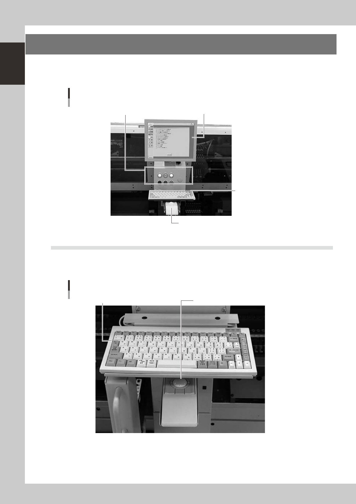
2.1 Keyboard and mouse
This machine is equipped with keyboards and trackballs as standard features to operate the machine or edit
data settings. To select a menu button or parameter item on the operation screen, place the cursor on it and
press the trackball button. (A keyboard and trackball are installed on the front and rear of the machine.)
Keyboard and trackball
Keyboard Trackball
23103-M3-00