YG300_Ope_E.pdf - 第74页
2-21 2 Basic operation 3 . 2 S t a r t i n g t h e m a c h i n e P r o c e e d a s f o l l o w s t o s t a r t t h e m a c h i n e . 1 T u r n t h e m a i n p o w e r O N . Tu r n o n t h e m a i n p o w e r s w i t c h …
2-20
2
Basic operation
3.1 Pre-operation check
e
Check the following points before turning on the power.
w
WARNING
ALWAYS BE SURE TO PRESS THE EMERGENCY STOP BUTTON BEFORE MAKING CHECKS.
n
Pre-operation checklist
Check item Checkpoint
Air
Check that the upper display on the air pressure gauge, which is at the front lower left of
the machine, shows 0.55Mpa.
Power supply
Check that the specified power is connected to the power supply box located behind the
front lower right panel of the machine.
Safety cover Check that the covers are closed.
Feeder Check that feeders are securely attached to the feeder plate and are not tilted.
Check that no chips or debris adhere to the feeders.
Conveyor Check that no chips or debris are on the conveyor.
Check that the conveyor units do not interfere with each other, such as push-up pins
under the conveyor rails.
Head Check that each nozzle is correctly installed to the head.
Nozzle
Check that the nozzle tips are not nicked, solder does not adhere to the nozzle tips, and
nozzle spring-action is smooth.
Feeder exchange
carriage (option)
Check that no chips or debris are on the feeder plate. Also check that the parts feeders
are securely attached to the feeder plate and no chips and debris adheres to them.
w
WARNING
THE SIGNAL LIGHT (SIGNAL TOWER) IS AN IMPORTANT DEVICE THAT SHOWS THE OPERATING STATUS OF THE MACHINE. THE
GREEN LAMP IS ON DURING OPERATION. THE YELLOW LAMP LIGHTS UP WHEN AN ERROR OR INTERLOCK OCCURS, AND
THE RED LAMP LIGHTS UP WHEN EMERGENCY STOP IS TRIGGERED. NEVER PLACE ANY PART OF THE BODY IN THE HEAD
MOVEMENT RANGE WHILE THE GREEN LAMP IS ON.
2-21
2
Basic operation
3.2 Starting the machine
Proceed as follows to start the machine.
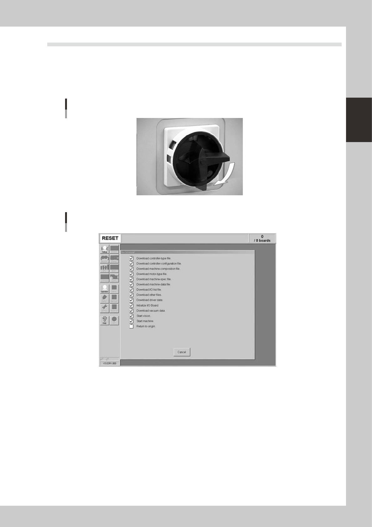
1
Turn the main power ON.
Turn on the main power switch at the front lower right of the machine, by turning it to the right. After the
system has started, the Initialization screen appears and the program necessary for machine operation
is loaded.
ON
OFF
Main Switch
23203-M3-00
Initialization screen
24211-M3-00
2
Perform return-to-origin.
The return-to-origin dialog box appears. Follow the instructions on the screen.
2-22
2
Basic operation
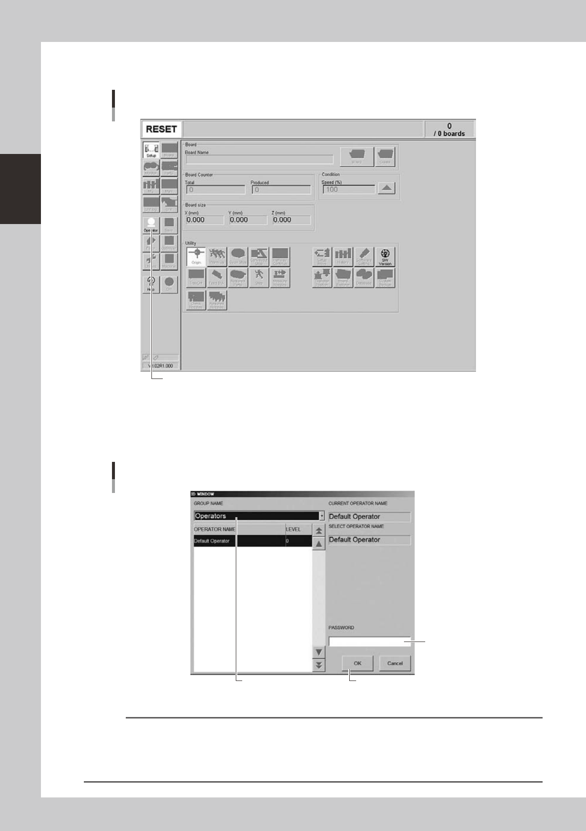
3
Press the [Operator] button.
The ID WINDOW dialog box appears for specifying the operator.
Press the [Operator] button to open the ID WINDOW.
[Operator] button
24212-M3-00
4
Specify the operator and enter the password.
As needed the operator "Administrator" or "Operator" can be selected from the GROUP NAME list. Then
enter the password and press the [OK] button. (If no password is set, just press the [OK] button.) When
the password is matched, the initial screen (Setup screen before selecting a board) appears.
Select the operator.
Enter the password.
Press [OK] after entering the password.
Specifying the operator
24213-M3-00
Reference
Active menu buttons differ depending on the operation level setup. For example, when the machine is turned on with
the factory setup, the program starts up at an operation level called "Default Operator". This "Default Operator" level is
set to "Level 0" at the time of shipment to allow only basic operation items. This operation level can be changed as
needed. Operators and operation items can also be added and specified by setting the password and operation
level.