YG300_Ope_E.pdf - 第110页
3-24 3 Starting and ending pr oduction • C o u n t D i s p l a y s t h e n u m b e r o f c o m p o n e n t s t h a t w e r e p i c k e d a n d p l a c e d b y t h e n o z z l e f o r w h i c h t h e p i c k u p p o s i t…
3-23
3
Starting and ending production
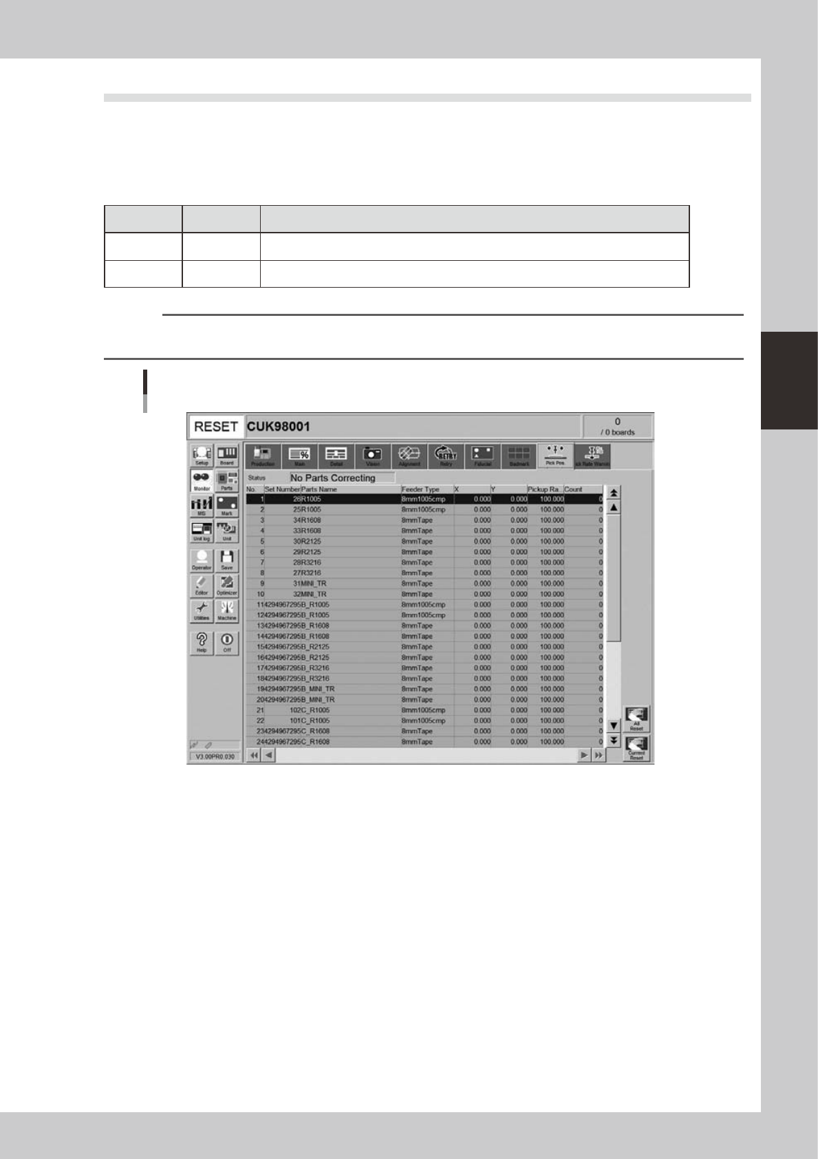
4.9 Pick Pos. (Pickup position offset)
This screen appears when the pickup position offset function is used. This screen shows how the pickup
position of the target component was corrected or offset. When the amount of offset in either the X or Y
direction crosses into a warning zone or error zone, the color of that row changes in real-time. The monitor
display color is shown below.
n
Display color
Color of row Status Description
Yellow Warning Exceeds warning level figure for each nozzle data in pickup position offset specifications.
Red Error Exceeds error level figure for each nozzle data in pickup position offset specifications.
n
NOTE
Numerical values for warning level and error levels set in the pickup position offset specifications are values
determined by the supervisor (administrator).
Monitor: Pick Pos. (Pickup position offset)
24311-M0-00
• No.
Displays the component No. (Parts screen data No.).
• Set No.
Displays the feeder set No.
• Parts Name
Displays the component name.
• Feeder Type
Displays the type of feeder.
• X (mm), Y (mm)
Displays the amount of pickup position offset after recognition. The figure shown is the amount of error from the nozzle
center position towards the X-direction and Y-direction.
• Pick Rate (%)
Displays the component pickup rate of the nozzle for which the pickup position offset function is on (enabled).

3-24
3
Starting and ending production
• Count
Displays the number of components that were picked and placed by the nozzle for which the pickup position offset
function is on (enabled).
• [All Reset] button
This button clears and resets pickup position offset data for all components shown on the monitor.
• [Current Reset] button
Clears and resets pickup position offset data for a component selected from among components shown on the monitor.
3-25
3
Starting and ending production
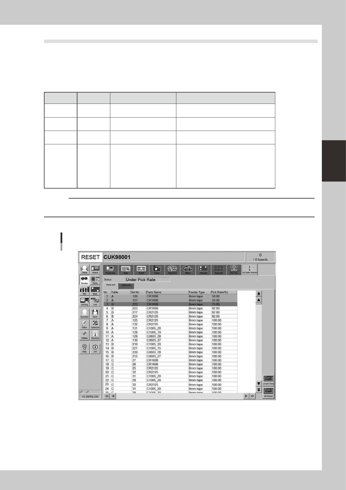
4.10 Pick Rate Warning
This screen appears when the pickup rate warning function is used. This screen allows checking for a drop in
the component pickup rate on each component or head. Clicking the tab to switch the display.
The pickup rate is reset in real-time after mounting a group of components. However, if a particular component
or head is not used then its row will not appear on the display. Pickup rates can be monitored by color during
operation.
n
Display color
Color of row Status Pickup Rate Description
White 100% to [caution (yellow)]%
Pickup rate is above [caution (yellow)]% and
below (or equal to) 100%.
Yellow Caution
[caution (yellow)]% to [warning
(red)]%
Pickup rate is above [warning (red)]% and
below (or equal to) [Caution (yellow)]%.
Red Warning [warning (red)]% to 0%
Pickup rate is above (or equal to) 0% and
below (or equal to) [warning (red)]%.
Pink
Watch-and-
wait mode
Optional
When the pickup rate is [warning (red)]%
or less, pressing the [Current Check] or [All
Check] button enables "watch-and-wait" mode
and the color of the "red" row(s) changes to
"pink".
Note that operation is not stopped in this mode
even if stop control setting is made.
n
NOTE
Numerical values (%) in brackets [ ] are machine data setting items, so an administrator right is required to change
them.
[Parts Info] tab
Monitor: Pick Rate Warning
Parts info
24318-M3-00
• No.
Displays the component No. (Parts screen data No.).
• Table
Displays the feeder table (feeder plate location) where the component feeder is installed.
• Set No.
Displays the feeder set position at which the component feeder is installed.