YG300_Ope_E.pdf - 第38页
1-10 1 Part names and functions n F e e d e r e x c h a n g e c a r r i a g e T h e f e e d e r p l a t e l a y o u t a n d s e t n u m b e r s d i f f e r d e p e n d i n g o n t h e m a c h i n e s p e c i f i c a t i …
1-9
1
Part names and functions
4. Component supply section
Components or parts are supplied from tape feeders installed on a feeder plate or from an external tray
changer or tray stacker. Under each feeder plate in the feeder setup section, power supply connectors and
air connectors are provided for driving optional units.
4.1 Supplying components from feeder plates
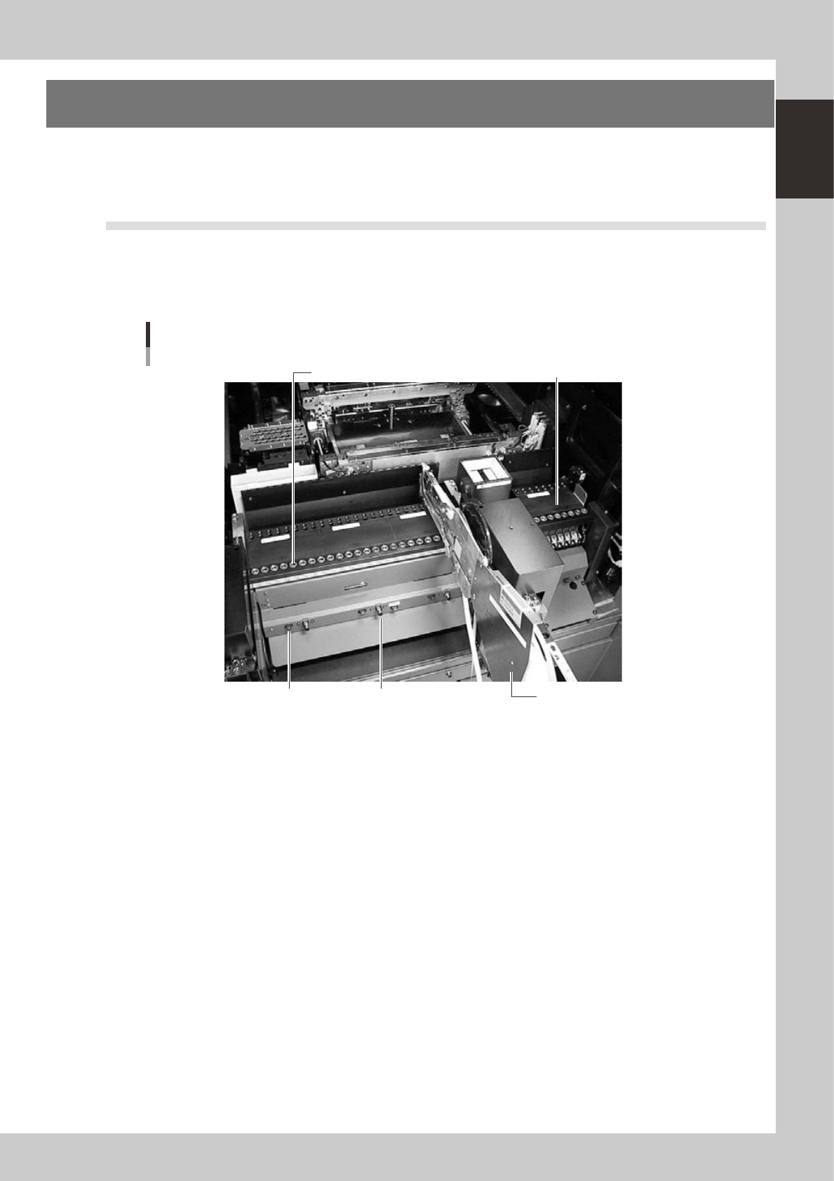
4.1.1 Fixed feeder plates
Tape feeders, bulk feeders and stick feeders are installed on the feeder plates, and operate by air supplied from
the mounter.
Feeder drive air outlet
Tape feeder (option)
Feeder plate
Power supply connector
Air connector
Feeder plate
23109-M3-00
Power supply connector
When using optional units such as stick feeders, plug the power cord into this connector.
Air connector
When using optional units such as stick feeders and air gun, connect the air tube (O.D. 4mm) to this air connector. Air is
supplied from the mounter to the connected unit. The feeder plate layout and set numbers differ depending on the
machine specifications. Typical feeder plate layouts are shown below. Some feeders cannot be reached by a head
depending on the head assembly configuration and X-axis movement range. The tables below show feeder set numbers
that can be accessed by each head.
1-10
1
Part names and functions
n
Feeder exchange carriage
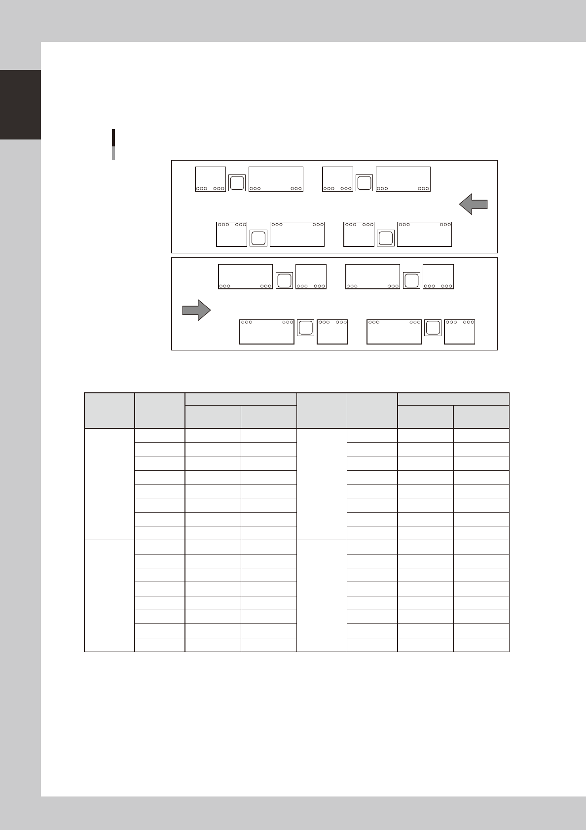
The feeder plate layout and set numbers differ depending on the machine specifications. Typical feeder plate layouts are
shown below.
Some feeders cannot be reached by a head depending on the head assembly configuration and X-axis movement range.
The tables below show feeder set numbers that can be accessed by each head.
1 25 3224 101 124 125 132
348 325 308 301 248 225 208 201
Feeder plate layout
1 25 488 101 108 125 148
332 325 324 301 232 225 224 201
Board
Board
Right-to-left
board flow
Left-to-right
board flow
D
C
D B B
C
A A
D
C
D B B
C
A A
23110-M3-00
Feeder types: Quick feeder exchange carriage
Table Head No.
Feeder set No.
Table Head No.
Feeder set No.
Right-to-left
board flow
Left-to-right
board flow
Right-to-left
board flow
Left-to-right
board flow
A 1 108 to 148 108 to 132 C 1 8 to 48 8 to 32
2 107 to 147 107 to 131 2 7 to 47 7 to 31
3 106 to 146 106 to 130 3 6 to 46 6 to 30
4 105 to 145 105 to 129 4 5 to 45 5 to 29
5 104 to 144 104 to 128 5 4 to 44 4 to 28
6 103 to 143 103 to 127 6 3 to 43 3 to 27
7 102 to 142 102 to 126 7 2 to 42 2 to 26
8 101 to 141 101 to 125 8 1 to 41 1 to 25
B 1 208 to 232 208 to 248 D 1 308 to 332 308 to 348
2 207 to 231 207 to 247 2 307 to 331 307 to 347
3 206 to 230 206 to 246 3 306 to 330 306 to 346
4 205 to 229 205 to 245 4 305 to 329 305 to 345
5 204 to 228 204 to 244 5 304 to 328 304 to 344
6 203 to 227 203 to 243 6 303 to 327 303 to 343
7 202 to 226 202 to 242 7 302 to 326 302 to 342
8 201 to 225 201 to 241 8 301 to 325 301 to 341
1-11
1
Part names and functions
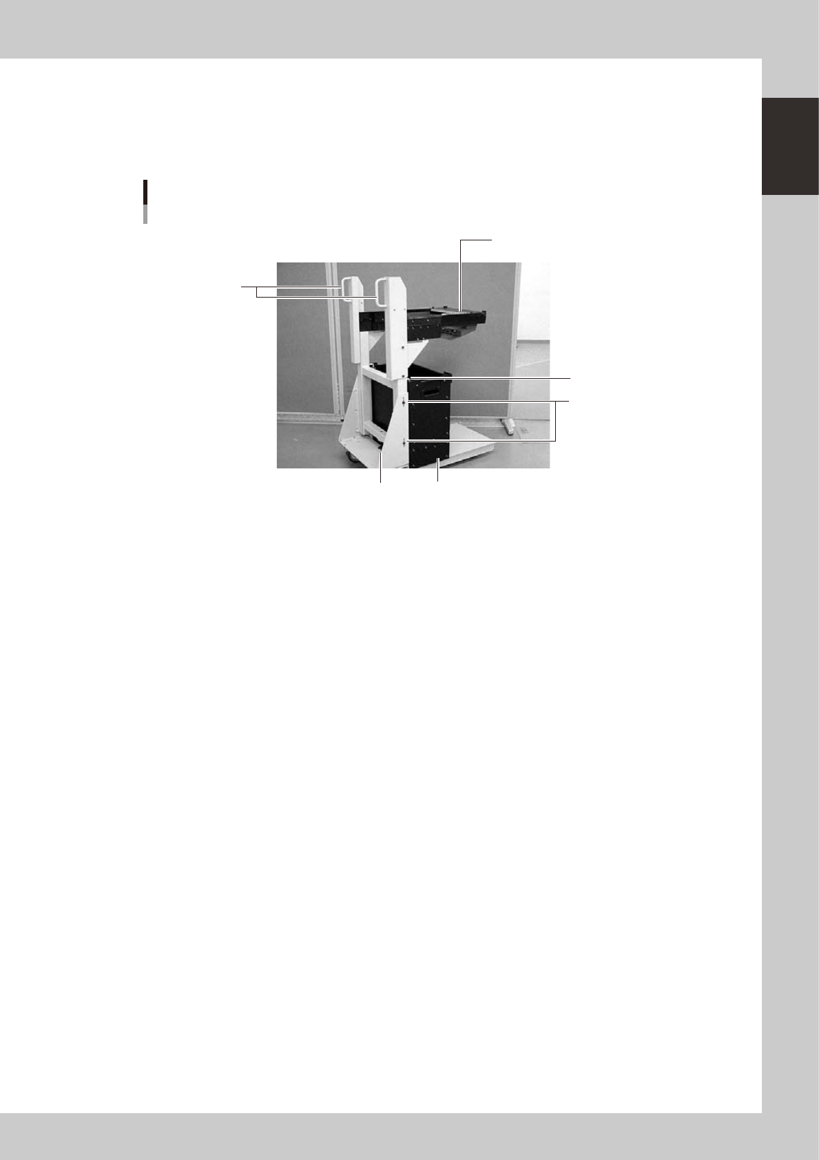
4.1.2 Feeder exchange carriage
The feeder exchange carriage allows feeder setup in advance for the next production boards. The feeders on
the feeder exchange carriage can be changed at one time.
n
Feeder exchange carriage
Feeder exchange carriage
1
2
5
4
6
3
23111-M3-00
1 Handle
Use this handle to move and position the feeder exchange carriage.
2 Feeder plate
Up to 20 or 24 tape feeders (8mm tape feeders) can be installed on this feeder plate.
3 Vertical clamp bolts
If necessary to adjust the feeder plate height, loosen these bolts and change their clamping positions by turning the
height adjustment bolt 6 to match the mounter height.
4 Empty tape dump box (option)
This box is for catching empty tape after components have been picked up.
5 Empty tape dump box holder
This holder prevents the tape dump box (option) from falling.
6 Height adjustment bolt
After loosening the vertical clamp bolts 3, turn this bolt to adjust the feeder plate height to match the mounter height.