YG300_Ope_E.pdf - 第47页
1-19 1 Part names and functions 9 . B l o w s t a t i o n O n e b l o w s t a t i o n i s i n s t a l l e d i n e a c h s t a g e . T h e b l o w s t a t i o n b l o w s h i g h - p r e s s u r e a i r i n t e r n a l l …
1-18
1
Part names and functions
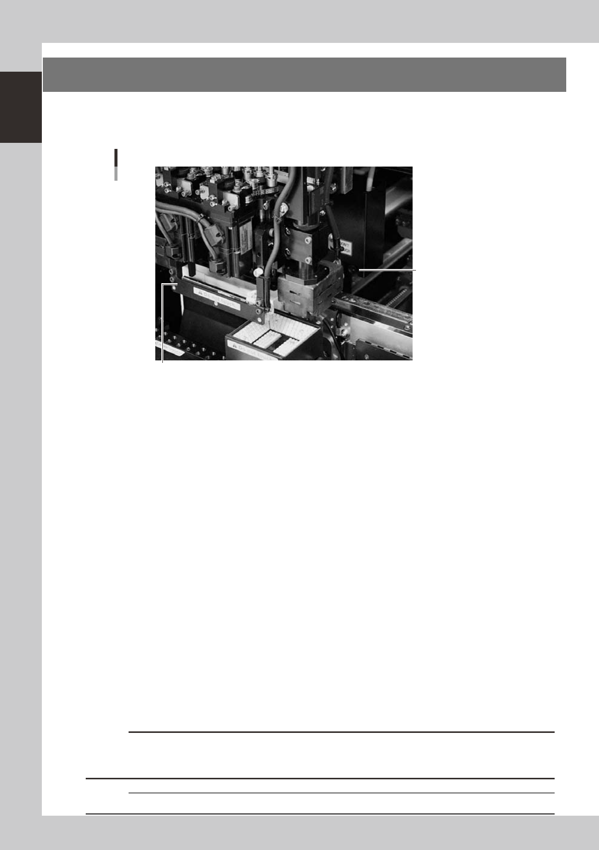
8. Side-view camera
The side-view camera is installed on the X-axis at the front of the multi-view camera. The side-view camera
recognizes horizontal images such as for the component pickup status, by using lighting installed for the
side-view camera. Use of the side-view camera allows detecting component pickup errors and dirt on each
nozzle.
Side-view camera
Side-view camera
Lighting unit for side-view camera (with cover removed)
23119-M3-00
The side-view camera has the following functions:
n
Pickup error detection function
Normal mode
Detects component pickup errors to prevent "no placement errors".
Normal mode operates even when nozzles are changed after nozzle cleaning, etc.
Detail mode
Detects component pickup errors to prevent "no placement errors".
Checks for abnormal component pickups such as tilted, vertical or horizontal pickups based on the component thickness
tolerance set by the users.
n
Dirty nozzle sensing function
If the side-view camera shows "no component" even when the multi-view camera shows "component present", the
machine determines that the nozzle tip is "dirty" and a warning message appears. This serves as an accurate guide for
nozzle cleaning periods.
n
Component discard skip
This function skips the discard operation when the side-view camera shows "no component".
This eliminates unneeded operation when no component was picked up and prevents a loss of cycle time during
production.
n
Remaining component check function
This detects whether a component still remains at a nozzle tip after components were mounted or discarded.
n
Inverted component check function
In the recognition process after a component is picked up by a nozzle, this function checks if the front and back sides of
the component are inverted. It also simultaneously checks if that component size fits within the angle-of-view of the
side-view camera.
An error message appears if recognition shows the component front and back sides are inverted or that component will
not fit within the angle-of-view.
c
CAUTION
This judgment might not be correct when checking components whose correct orientation is with leads on the upper
half of the component or components whose side surface image is a rectangular parallelepiped (chip capacitors,
etc.).
n
NOTE
Refer to "Programming Manual" for side-view camera parameter settings.
1-19
1
Part names and functions
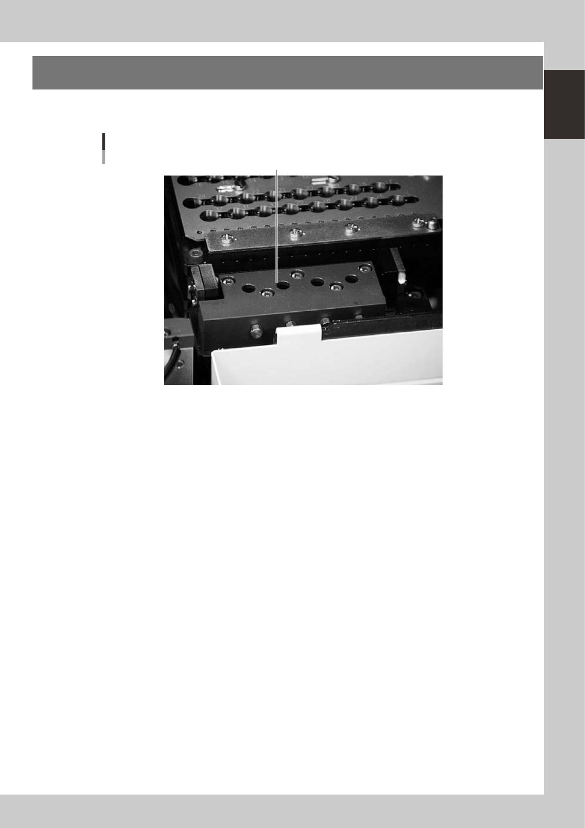
9. Blow station
One blow station is installed in each stage. The blow station blows high-pressure air internally through the
nozzles and shafts to blow away dust and grit and clean the nozzles.
Blow station
Blow station
23120-M3-00
1-20
1
Part names and functions
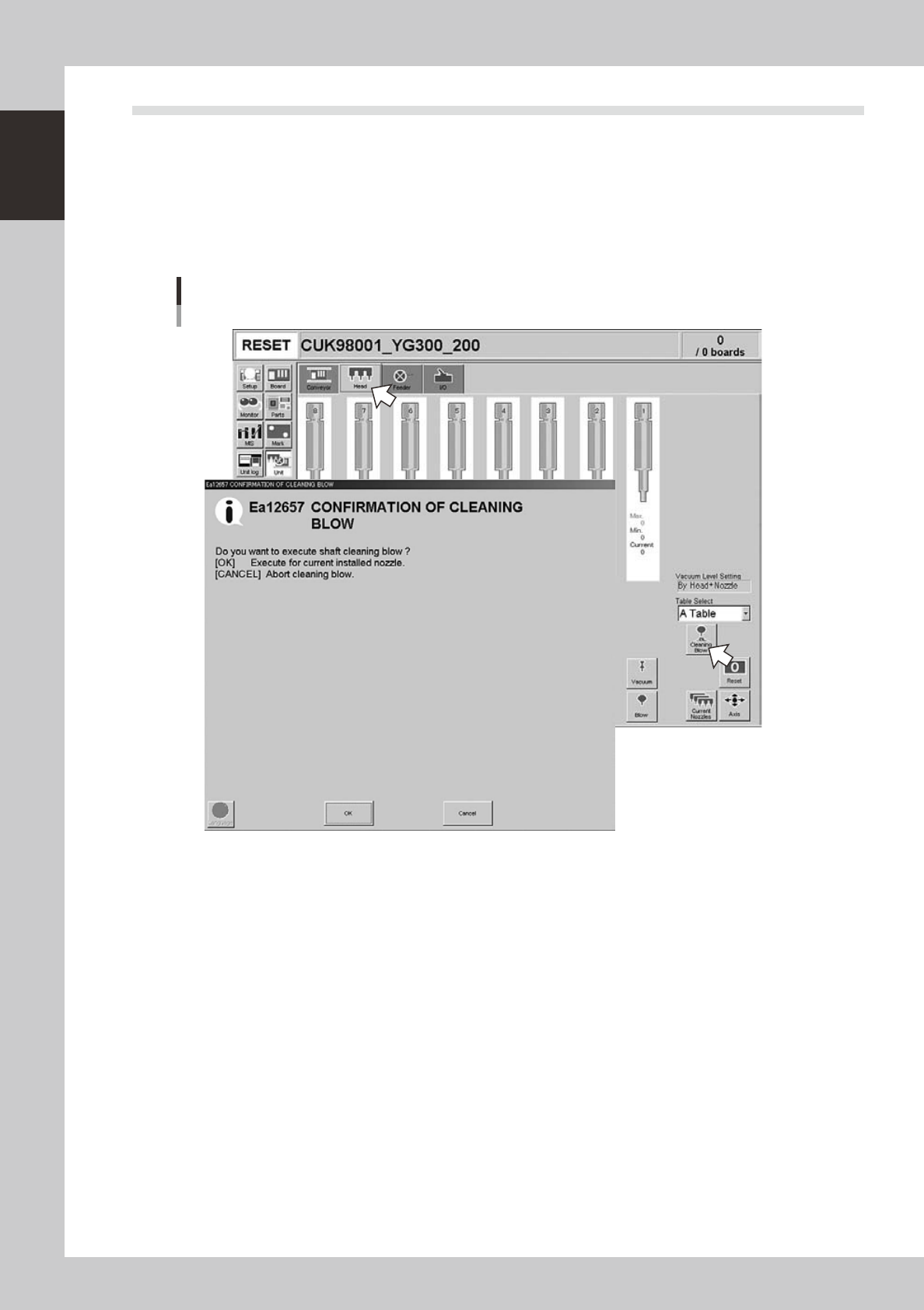
9.1 Performing a nozzle shaft blow
This section explains how to manually perform a nozzle shaft blow at any desired timing.
1
Open the [Unit] – [Head] tab screen.
2
Press the [Cleaning Blow] button.
A confirmation dialog box appears asking whether to perform nozzle shaft blow.
Press the [OK] button to perform nozzle shaft blow and proceed to the next step. If you want to cancel
nozzle shaft blow, press the [Cancel] button.
Nozzle shaft blow
24100-M3-00