YG300_Ope_E.pdf - 第35页
1-7 1 Part names and functions 3 . 2 N o z z l e t y p e s T o e n s u r e s t a b l e c o m p o n e n t p i c k u p , t h e c o r r e c t n o z z l e t h a t m a t c h e s t h e c o m p o n e n t m u s t b e u s e d . T…
1-6
1
Part names and functions
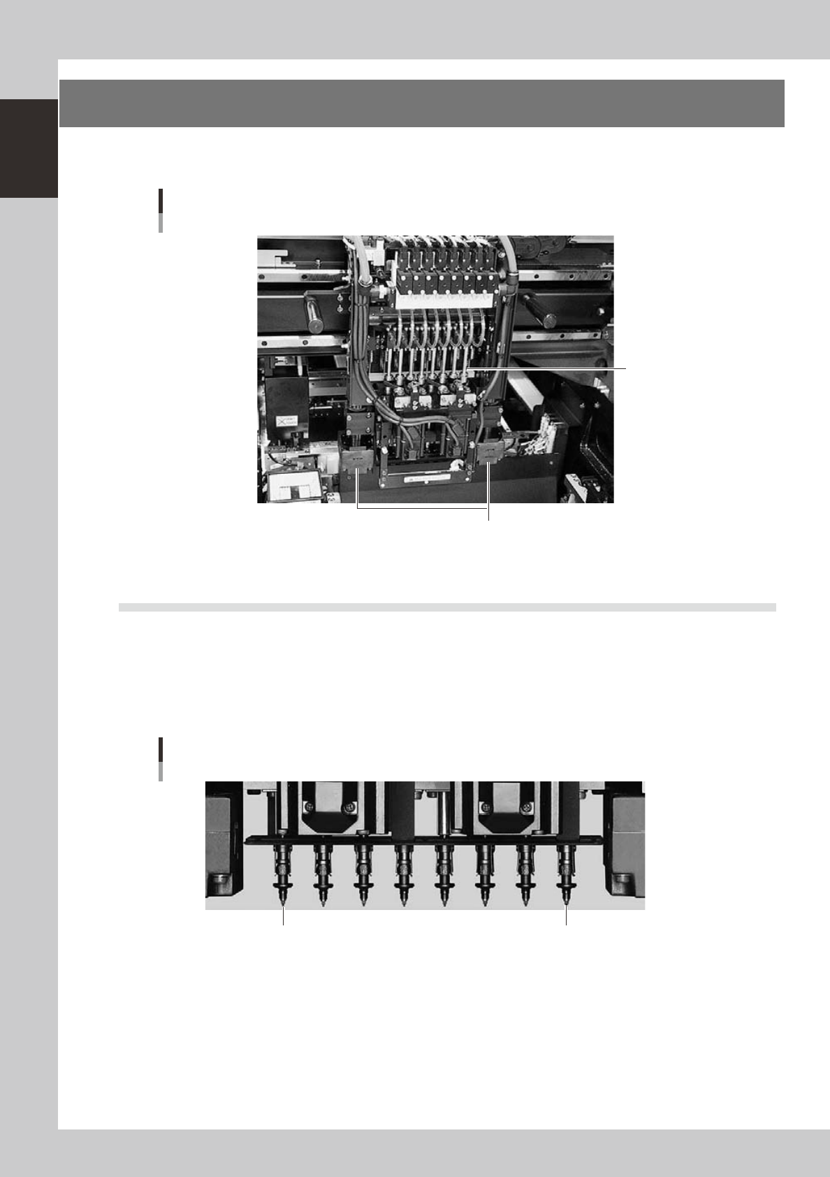
3. Head assembly
The head assembly is mounted on the XY arms and moves to pick up and place components. The following
sections describe the head assembly configurations and nozzle types.
head assembly
Moving camera/Lighting unit
Inner side: Fiducial camera
Outer side: Teaching camera
Eight-in-line multi-head
23115-M3-00
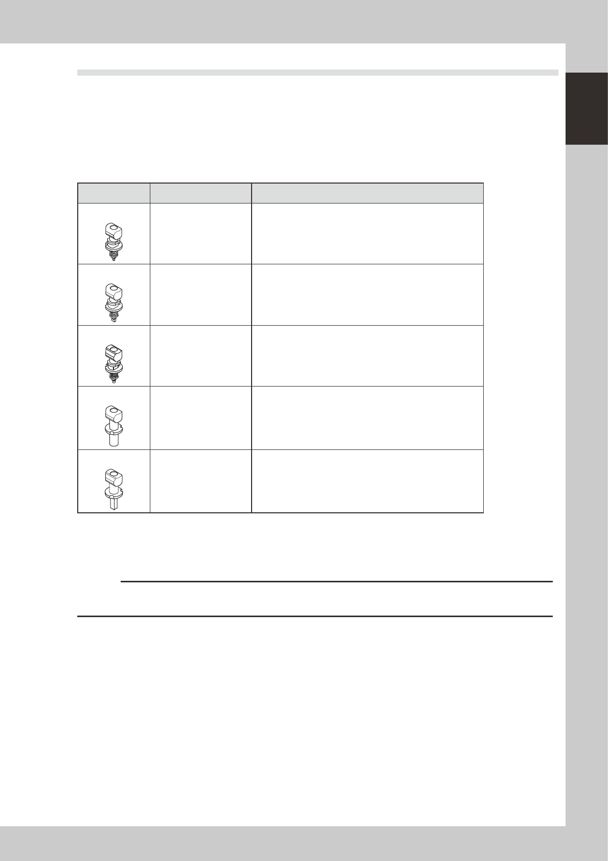
3.1 Component pick-and-place head
3.1.1 Eight-in-line multi-head (FNC) assembly
The eight-in-line multi-head assembly has 8 heads arranged in a row to pick up and mount components at high
speeds. Head numbers are designated from 1 to 8, from the right as viewed from the front of the head
assembly. The spacing of adjacent nozzles attached to the head assembly is 16mm, which is identical to the
pitch of the feeder installation holes on the feeder plates.
Head 8 Head 1
Eight-in-line multi-head
23105-M3-00
1-7
1
Part names and functions
3.2 Nozzle types
To ensure stable component pickup, the correct nozzle that matches the component must be used. The
following sections explain typical nozzles which can be attached to each head.
3.2.1 Nozzles for the eight-in-line head assemblies
On the eight-in-line multi-head assembly, five types of standard nozzles can be chosen and attached to each
head.
n
eight in-line multi-head type nozzle
Nozzle Type Head No. Typical Components
Type 301A
1 to 8 0603 to 1005 size chip components, mini-mold transistors, etc.
Type 302A
1 to8 1608 to 3216 size chip components, mini-mold transistors, etc.
Type 309A
1 to8 1608 to 3216 size chip components, mini-mold transistors, etc.
Type 303A
1 to8
4532 to 7343 size components, 10 mm SOP,
5×5mm to 14×14mm QFP, etc.
Type 306A
1 to8 Cylindrical chip (MELF) only
* Type 302A and Type 309A nozzles cannot be selected at the same time.
Type A nozzles
Type A nozzles (301A, 302(309)A, 303A, 306A) can be attached to all heads of the eight-in-line head assembly.
c
CAUTION
The above nozzles are specifically designed for use with the YG300 surface mounters. Do not use them for other
machines. Also, do not use the other machines' nozzles for this machine.
1-8
1
Part names and functions
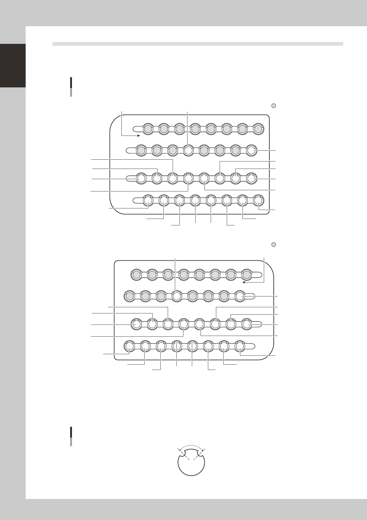
3.3 Nozzle station (option)
The nozzle station accommodates various nozzles for automatic change.
The YG300 with an optional nozzle station enables automatic nozzle change on all heads.
The drawings below show the nozzle station No. and the allotted head No. and mating nozzle type.
Nozzle station
13141516
1720
2526272829303132
21222324 1819
9101112
5678 1234
Custom nozzle pockets
Station No.
HEAD1
TYPE 303A
HEAD5
TYPE 303A
HEAD2
TYPE 302A,309A
HEAD3
TYPE 302A,309A
HEAD4
TYPE 302A,309A
HEAD6
TYPE 302A,309A
HEAD7
TYPE 302A,309A
HEAD8
TYPE 302A,309A
HEAD5
TYPE 302A,309A
HEAD1
TYPE 302A,309A
HEAD2
TYPE 301A
HEAD3
TYPE 301A
HEAD4
TYPE 301A
HEAD5
TYPE 301A
HEAD6
TYPE 301A
HEAD7
TYPE 301A
HEAD8
TYPE 301A
HEAD1
TYPE 301A
N Tables A and D
13141516
1720
2526272829303132
21222324 1819
9101112
5678 1234
Custom nozzle pockets
Station No.
HEAD1
TYPE 303A
HEAD5
TYPE 303A
HEAD2
TYPE 302A,309A
HEAD3
TYPE 302A,309A
HEAD4
TYPE 302A,309A
HEAD6
TYPE 302A,309A
HEAD7
TYPE 302A,309A
HEAD8
TYPE 302A,309A
HEAD5
TYPE 302A,309A
HEAD1
TYPE 302A,309A
HEAD2
TYPE 301A
HEAD3
TYPE 301A
HEAD4
TYPE 301A
HEAD5
TYPE 301A
HEAD6
TYPE 301A
HEAD7
TYPE 301A
HEAD8
TYPE 301A
HEAD1
TYPE 301A
N Tables B and C
23107-M3-00
n
Nozzle notch angle
The nozzles for the YG300 have notches as shown below for identifying their position in the station. The
q
(theta) angle
here is called the notch angle. The notch angles on Type 301A and Type 302A(309A) nozzles are respectively 90 and 60
degrees. The notches on the special nozzles 303A and 306A are 120 degrees.
Nozzle notch angle
Q
23108-M3-00