YG300_Ope_E.pdf - 第45页
1-17 1 Part names and functions 7 . A x i s c o n f i g u r a t i o n T h e m a c h i n e a x i s c o n f i g u r a t i o n a n d o p e r a t i o n a r e s h o w n i n t h e d r a w i n g a n d t a b l e b e l o w. Plus …
1-16
1
Part names and functions
A
BCD
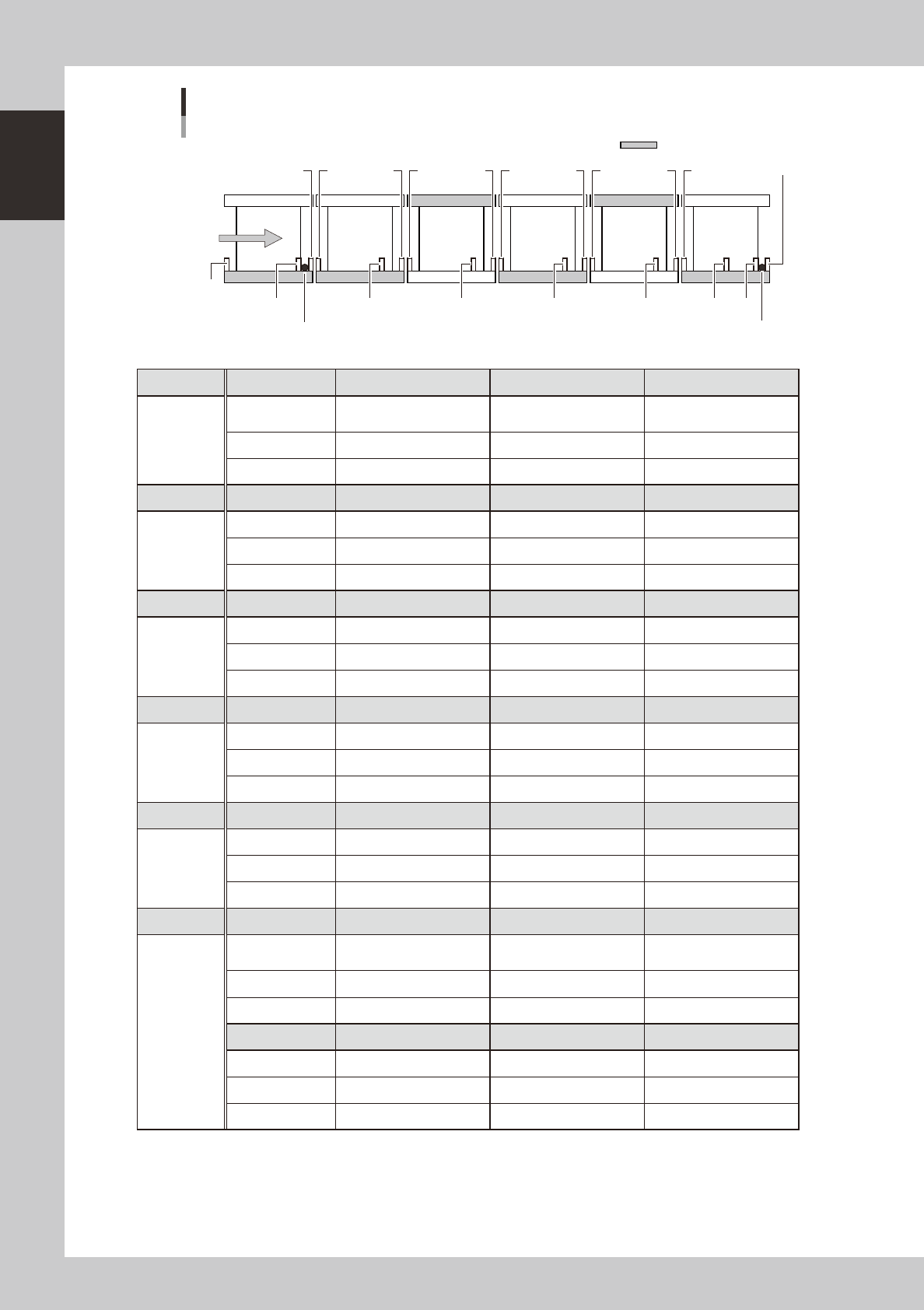
Conveyor sensor positions
Left-to-right board flow
19
16
Reference (fixed) conveyor
Left conveyor
Right conveyor
Board
151312109
8
76
52
43
1
1411
Exit stopper
Standby stopper
17
18
23117-M3-00
Unit No. 1 2 3
Left
conveyor
Use Entrance detection
Standby position
detection
Hazard detection
Address N0100792 N0100793 N0100794
Name IN_CONV_CONV6_ENT IN_CONV_CONV6_RCV IN_CONV_CONV6_END
Unit No. 4 5 6
Stage D Use Hazard detection Board detection Hazard detection
Address N0100824 N0100825 N0100826
Name IN_CONV_CONV5_ENT IN_CONV_CONV5_RCV IN_CONV_CONV5_END
Unit No. 7 8 9
Stage C Use Hazard detection Board detection Hazard detection
Address N0100811 N0100812 N0100813
Name IN_CONV_CONV4_ENT IN_CONV_CONV4_RCV IN_CONV_CONV4_END
Unit No. 10 11 12
Stage B Use Hazard detection Board detection Hazard detection
Address N01006A4 N01006A5 N01006A6
Name IN_CONV_CONV3_ENT IN_CONV_CONV3_RCV IN_CONV_CONV3_END
Unit No. 13 14 15
Stage A Use Hazard detection Board detection Hazard detection
Address N0100691 N0100692 N0100693
Name IN_CONV_CONV2_ENT IN_CONV_CONV2_RCV IN_CONV_CONV2_END
Unit No. 16 17 18
Right
conveyor
Use Hazard detection
Intermediate position
detection
Exit detection
Address N0100612 N0100615 N0100613
Name IN_CONV_CONV1_ENT IN_CONV_CONV1_RCV IN_CONV_CONV1_RCV
No. 16
Use Hazard detection
Address N0100614
Name IN_CONV_CONV1_END
1-17
1
Part names and functions
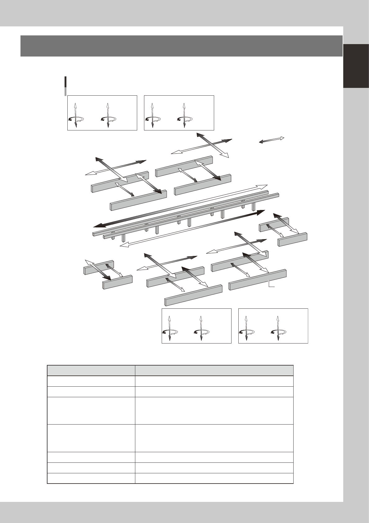
7. Axis configuration
The machine axis configuration and operation are shown in the drawing and table below.
Plus direction
Minus direction
YB axis
YA axis
T1 axis
T2 axis
YC axis
UD axis
UB axis
UA axis
UC axis
UR axis
UL axis
WB axis
Axis configuration
ZC5 to 8 axis
RC2 axis
ZC1 to 4 axis
RC1 axis
Head unit C
ZA5 to 8 axis
RA2 axis
ZA1 to 4 axis
RA1 axis
Head unit A
Conveyor rail
ZD1 to 4 axis
RD1 axis
ZD5 to 8 axis
RD2 axis
Head unit D
ZB1 to 4 axis
RB1 axis
ZB5 to 8 axis
RB2 axis
Head unit B
WA axis
YD axis
XD axis
XC axis
XB axis
XA axis
WR axis
WL axis
WD axis
WC axis
23111-M1-00
n
Function of each axis
Axis Function
XA, XB, XC, XD Moves the head assembly in parallel with the board flow.
YA, YB, YC, YD Moves the head assembly perpendicular to the board flow.
ZA1 to ZA8
ZB1 to ZB8
ZC1 to ZC8
ZD1 to ZD8
Controls the height of each component pick-and-place head.
RA1, RA2
RB1, RB2
RC1, RC2
RD1, RD2
Rotates the nozzle shafts of each head.
WA, WB, WC, WD, WL, WR Changes the conveyor width of each stage.
T1, T2 Transfers a board on each stage while gripping the board edges.
UA, UB, UC, UD, UL, UR Moves each stage in the Y direction.
1-18
1
Part names and functions
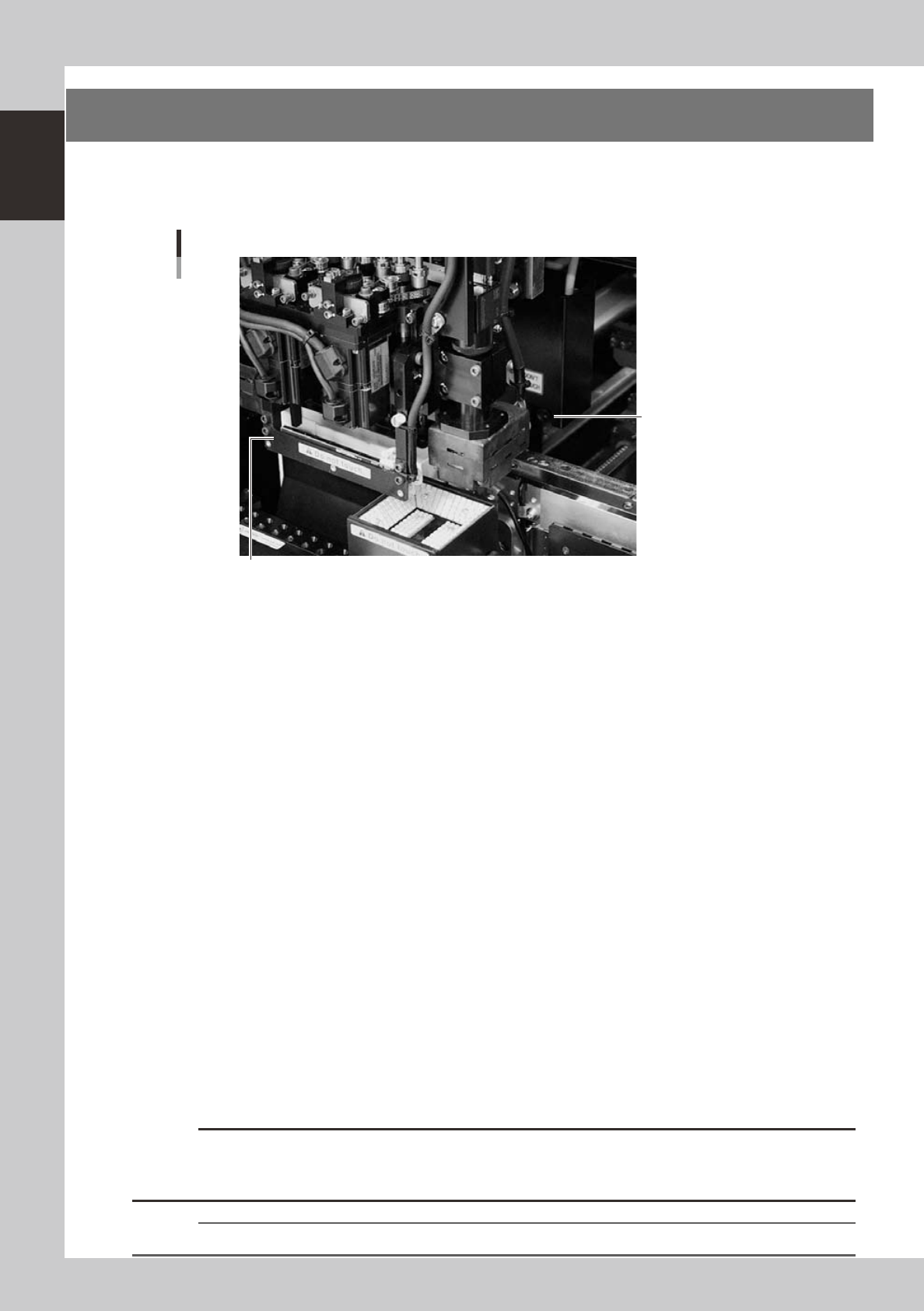
8. Side-view camera
The side-view camera is installed on the X-axis at the front of the multi-view camera. The side-view camera
recognizes horizontal images such as for the component pickup status, by using lighting installed for the
side-view camera. Use of the side-view camera allows detecting component pickup errors and dirt on each
nozzle.
Side-view camera
Side-view camera
Lighting unit for side-view camera (with cover removed)
23119-M3-00
The side-view camera has the following functions:
n
Pickup error detection function
Normal mode
Detects component pickup errors to prevent "no placement errors".
Normal mode operates even when nozzles are changed after nozzle cleaning, etc.
Detail mode
Detects component pickup errors to prevent "no placement errors".
Checks for abnormal component pickups such as tilted, vertical or horizontal pickups based on the component thickness
tolerance set by the users.
n
Dirty nozzle sensing function
If the side-view camera shows "no component" even when the multi-view camera shows "component present", the
machine determines that the nozzle tip is "dirty" and a warning message appears. This serves as an accurate guide for
nozzle cleaning periods.
n
Component discard skip
This function skips the discard operation when the side-view camera shows "no component".
This eliminates unneeded operation when no component was picked up and prevents a loss of cycle time during
production.
n
Remaining component check function
This detects whether a component still remains at a nozzle tip after components were mounted or discarded.
n
Inverted component check function
In the recognition process after a component is picked up by a nozzle, this function checks if the front and back sides of
the component are inverted. It also simultaneously checks if that component size fits within the angle-of-view of the
side-view camera.
An error message appears if recognition shows the component front and back sides are inverted or that component will
not fit within the angle-of-view.
c
CAUTION
This judgment might not be correct when checking components whose correct orientation is with leads on the upper
half of the component or components whose side surface image is a rectangular parallelepiped (chip capacitors,
etc.).
n
NOTE
Refer to "Programming Manual" for side-view camera parameter settings.