YG300_Ope_E.pdf - 第61页
2-8 2 Basic operation 2 . O p e r a t i o n s c r e e n a n d b u t t o n s T h e b a s i c c o n f i g u r a t i o n a n d o p e r a t i o n m e t h o d s o f t h e s o f t w a r e s c r e e n s a r e e x p l a i n e d …
2-7
2
Basic operation
n
Others
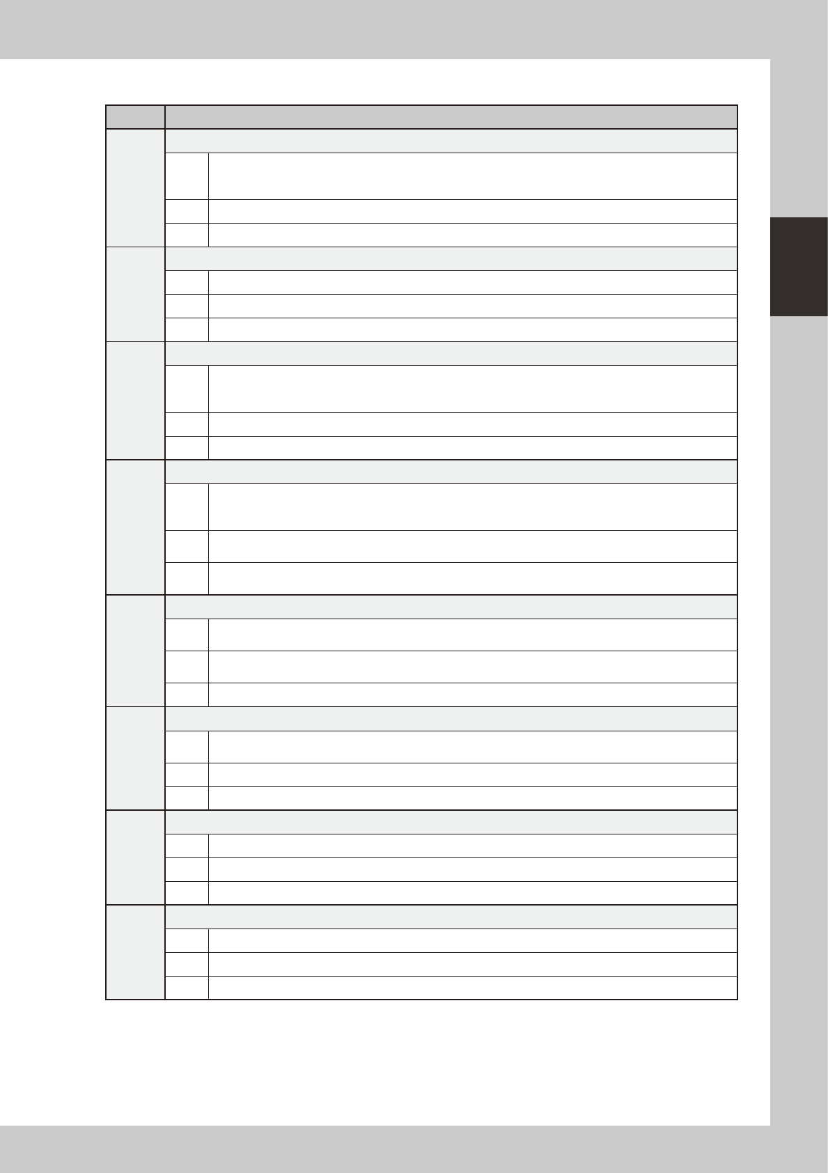
Code Error name and description
Ea00109
EMERGENCY STOP FUNCTION DURING MOUNT
State
EMERGENCY STOP FUNCTION is executed duringmounting sequense. So, there is danger that
mountsequense finished under the unusual condition. Can it stop automatically after it installs it when an
automatic driving is restarted, and the image at the installation position be confirmed.
Cause Emergency stop was triggered during component placement.
Action Use "trace" to check whether the component is placed at the specified point.
Ea00818
QUICK STOP ACTIVE
State QUICK STOP FUNCTION is now active.
Cause Emergency stop was triggered by the "conveyor width safety check sensor".
Action Check the status of the conveyor width safety check sensor.
Ea01023
WARNING: NOT ENOUGH HDD SPACE
State
Free space on Hard Disk is less than 10MB. To avoid the possibility that you cannot save new data anymore
and that data might be lost, it is best to create new space on the hard disk now. Copy unused Board data to
floppy disks and delete it from the hard disk.
Cause Board data are too many.
Action Make a backup of unnecessary board data and delete those data from the hard disk.
Ea02722
DON'T YOU NEED HALFWAY CONTINUE?
State
A board that is not finished to mount exist on the mounting position. If you continue auto running, a halfway
board may be transferred. Please confirm the board condition and execute halfway continue command if
necessary.
Cause
A board for which component mounting is not completed is left in the component placement position. If
automatic operation continues as is, then the unfinished board may be transferred downstream.
Action
Check the board in the component placement position. When it is not finished, run "Halfway Continue"
command to resume component mounting on that board.
Ea02889
EMERGENCY STOP FUNCTION DURING PICK
State
EMERGENCY STOP FUNCTION is executed during picking sequence. There is a chance that the picking
sequence finished under suspicious conditions. Please check condition of the component.
Cause
Emergency stop was triggered during component pickup. Component pickup operation might have been
unstable.
Action Check how the component is being picked up.
Ea07871
CAN NOT EXECUTE COMMAND
State
Can not execute this command , because RESET is not finished completely. Please try the RESET command
again, and finish it.
Cause Unable to run commands since reset is not complete.
Action Perform a reset again.
Ea01277
X1 Axis 2nd LIMIT OVER
State Move the axis until error message disappears. The "EMERGENCY STOP" light will go off.
Cause X1-axis secondary limit was exceeded.
Action Move the X1 axis by hand to a safe position.
Ea01278
Y1 Axis 2nd LIMIT OVER
State Move the axis until error message disappears. The "EMERGENCY STOP" light will go off.
Cause Y1-axis secondary limit was exceeded.
Action Move the Y1 axis by hand to a safe position.
2-8
2
Basic operation
2. Operation screen and buttons
The basic configuration and operation methods of the software screens are explained in this section. Please
read through this section before operating the machine.
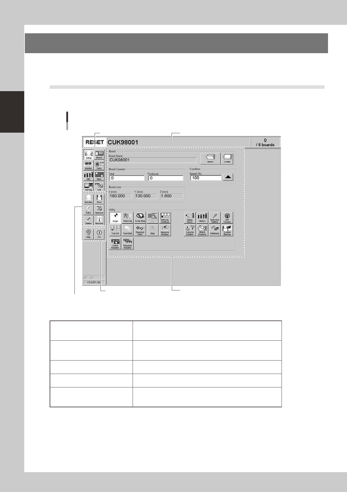
2.1 Basic configuration of operation screen
The YG series operation screen can be divided into the "Status area", "Main menu button area" and "Submenu
button and parameter area" as shown below.
Main menu button area 1
Main menu button area 2
Main menu button area 3
Status area
Operation screen basic configuration
Setup screen
Submenu button and parameter area
24200-M3-00
n
Area on screen
Status area
Displays the current machine status on the left end, the selected board
name in the middle, and the number of boards that have been produced
on the right end.
Main menu button area 1
Shows the main menu buttons used to operate the machine. The
submenu button and parameter area will change according to the
selected main menu button.
Main menu button area 2
Shows the menu buttons used to call up auxiliary functions of the
machine.
Main menu button area 3
Shows the [Help] button to call up the help screen and also the [Off]
button to quit the software.
Submenu button and parameter area
Displays the submenu buttons and parameters for machine operation
and data setting. This area will change according to the selected main
menu button.
2-9
2
Basic operation
n
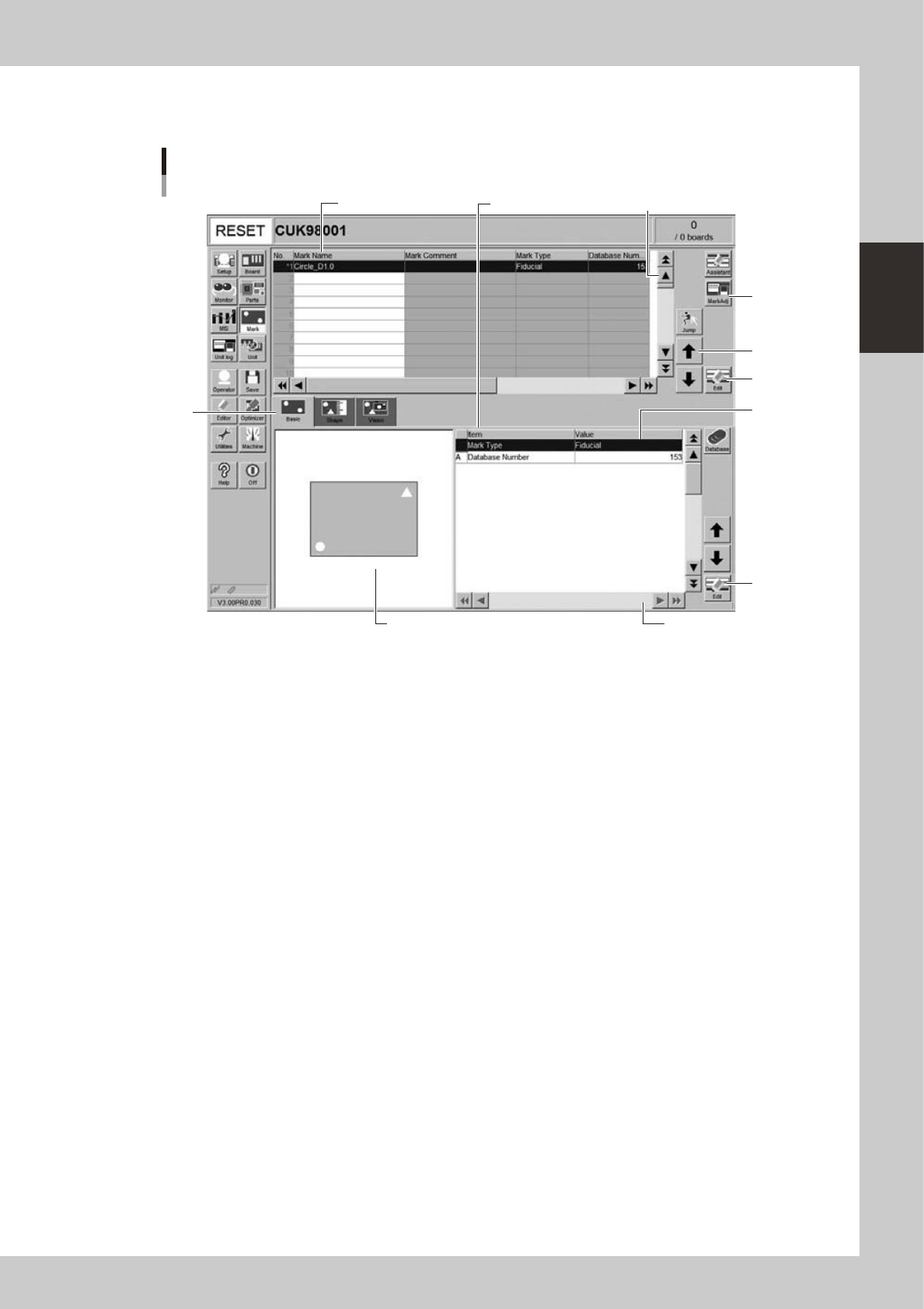
Various buttons and parameter input boxes
Various types of buttons, selection tabs and parameter input boxes are used on the operation screen.
1
1
2
3
4
5
6
7
Operation screen basic elements
Mark screen
Parameter list
Data No. list
5
24201- M3-00
1. Scroll bar and button (Up/down, right/left)
Use the scroll bars or arrow buttons to see hidden items in the parameter list.
2. Operation button
Press these buttons to open the next operation screen or dialog box.
3. Line up/down button
Use these buttons to move the cursor up or down through the parameter list.
4. Parameter input box
Select, enter or edit parameters here. When the keyboard is used, double-click on a parameter input box to enter or edit
the data.
When a touch screen (option) is used, press the [Edit] button on the lower right of the parameter list. The edit box then
pops up for data input and editing.
5. Edit button
Press this button to open the edit dialog box for the selected parameter item.
6. Selection tab
Select this tab to switch the parameter input screen.
7. Assistant screen
Shows an illustration or information useful for parameter input or editing. Alphabet characters shown in the parameter
list and in the illustration on this screen correspond to each other.