Process Lens PL Service Manual_EN.pdf - 第105页
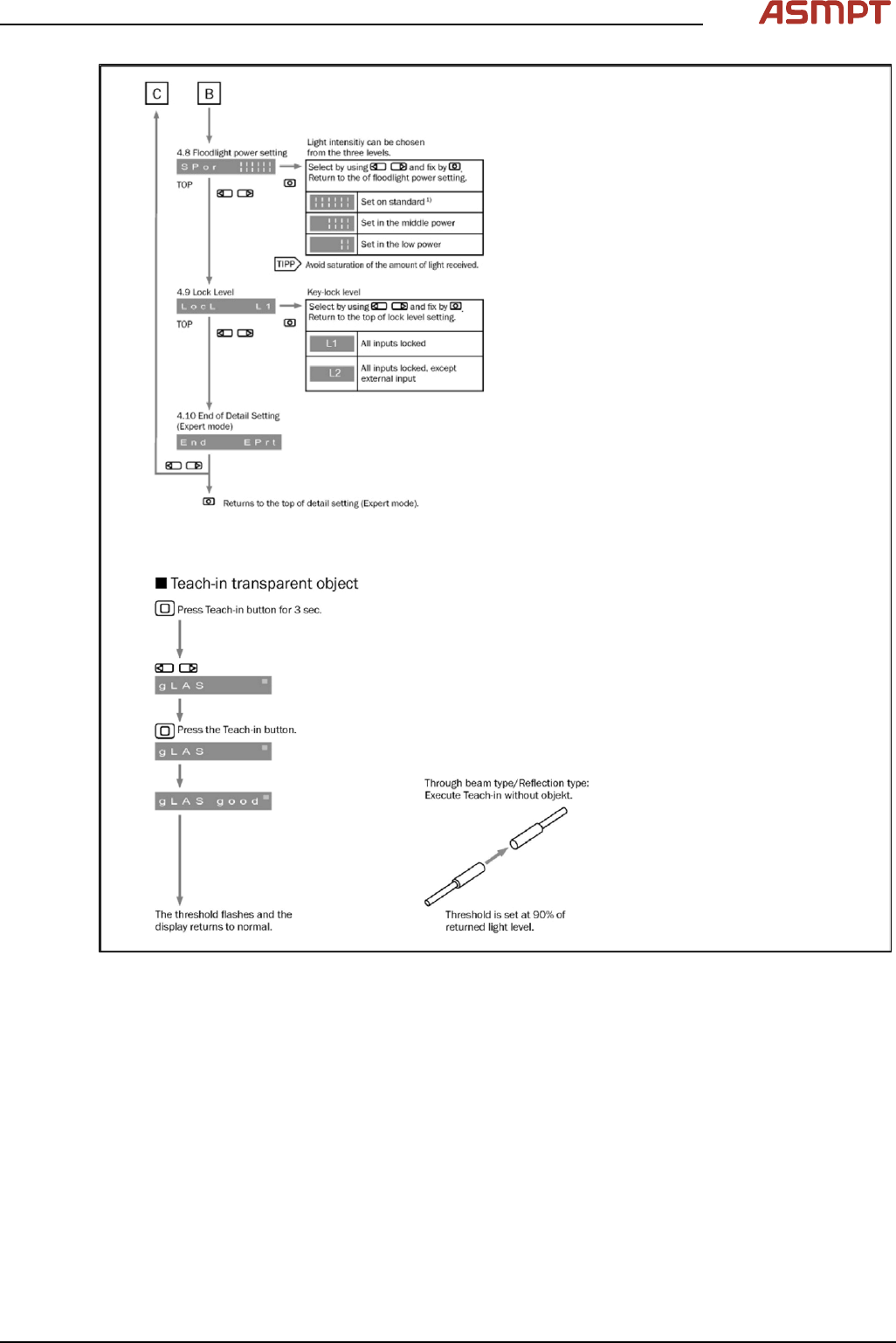
3 Replacing spare parts Se rv ic e Ma nu al P ro ce ss L en s PL - 0 3/ 20 25 10 5 Fig.143: Setting the fiber optic sensor - 4
3 Replacing spare parts
104 Service Manual Process Lens PL - 03/2025
Fig.142: Setting the fiber optic sensor - 3
3 Replacing spare parts
Service Manual Process Lens PL - 03/2025 105
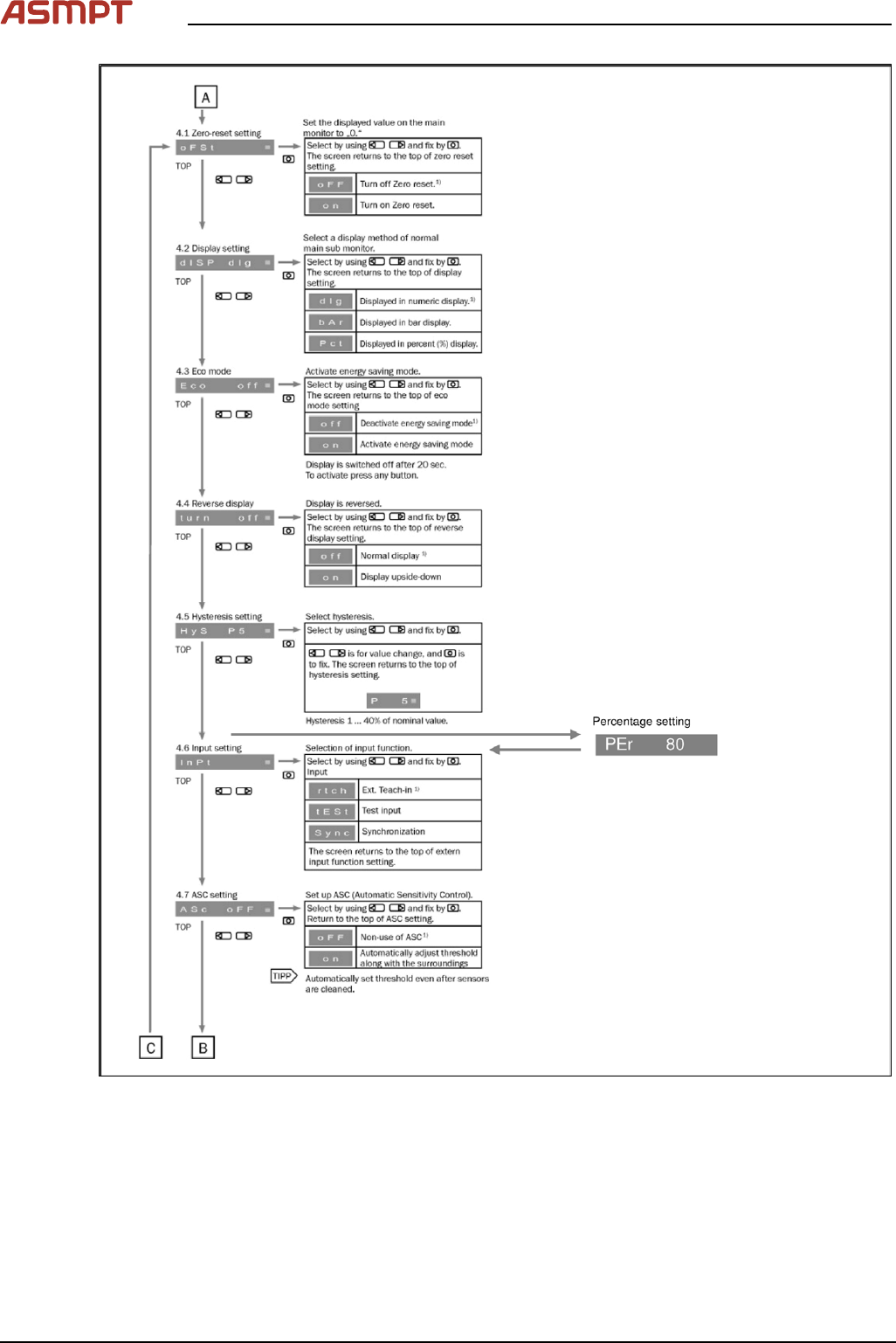
Fig.143: Setting the fiber optic sensor - 4
3 Replacing spare parts
106 Service Manual Process Lens PL - 03/2025
Replacing laser light barrier cables and fiber optic cables
Parts
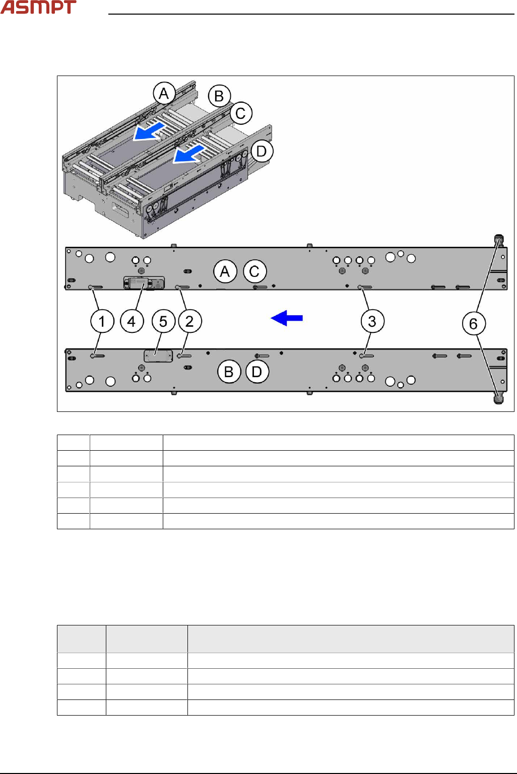
Fig.144: Laser light barriers and fiber optic cables
1 03092408-xx Fiber optic cable LL3-TV05 3m
2 03092408-xx Fiber optic cable LL3-TV05 3m
3 03092407-xx Fiber optic cable LL3-TV05 2m
4 03098280‑xx Laser light barrier transmitter*
5 03098281‑xx Laser light barrier receiver*
6 Cable outlet on the input side of the rail
* See also 3.5.1.6.1 "Replacing the laser light barrier for the transmitter/receiver" [}92]
The fiber optic cables are routed through the conveyor rail to the cable outlet(6). From there, the fiber
optic cables are routed under the lifting table to the fiber optic sensors.
The laser light barrier cables are routed through the conveyor rail to the cable outlet(6). From there,
the cables are routed under the lifting table to the conveyor control.
Laser light barrier cable transmitter and receiver
Side
panel
Item no. Designation
A 03113845-xx Cable PCB centering laser LLBt1 panel-A
B 03113846-xx Cable PCB centering laser LLBt1 panel-B
C 03113847-xx Cable PCB centering laser LLBt2 panel-C
D 03113848-xx Cable PCB centering laser LLBt2 panel-D
See also Replacing the cables (belt motor and width adjustment motor)