Process Lens PL Service Manual_EN.pdf - 第23页
3 Replacing spare parts Se rv ic e Ma nu al P ro ce ss L en s PL - 0 3/ 20 25 23 Fig.7: Removing the screws ► Remove the screws (1) fixing the optical head at the machine using an Allen key size 2.5. Start from the bot…
3 Replacing spare parts
22 Service Manual Process Lens PL - 03/2025
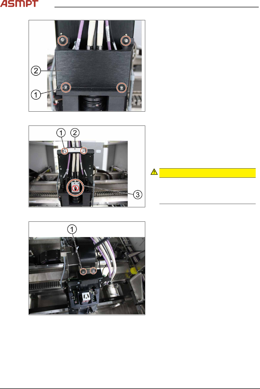
Fig.4: Removing the cover
► Remove the cover(2) that protects the
connection spots for the cables by un-
screwing the screws(1) by using an Allen
key size 2.5.
► Place the dismantled cover on a service
table.
Fig.5: Unplugging the cables
► Remove the cable clamp(2) that fixes the
cables by unscrewing the screws(1) using
an Allen key size 2.5.
► Place the dismantled cable clamp(2) on a
service table.
► Unplug the cables.
CAUTION!
Sensitive camera system
The camera system (3) is very sensitive.
Therefore do not touch the camera sys-
tem to avoid damage to it.
.
► Carefully put the cables aside.
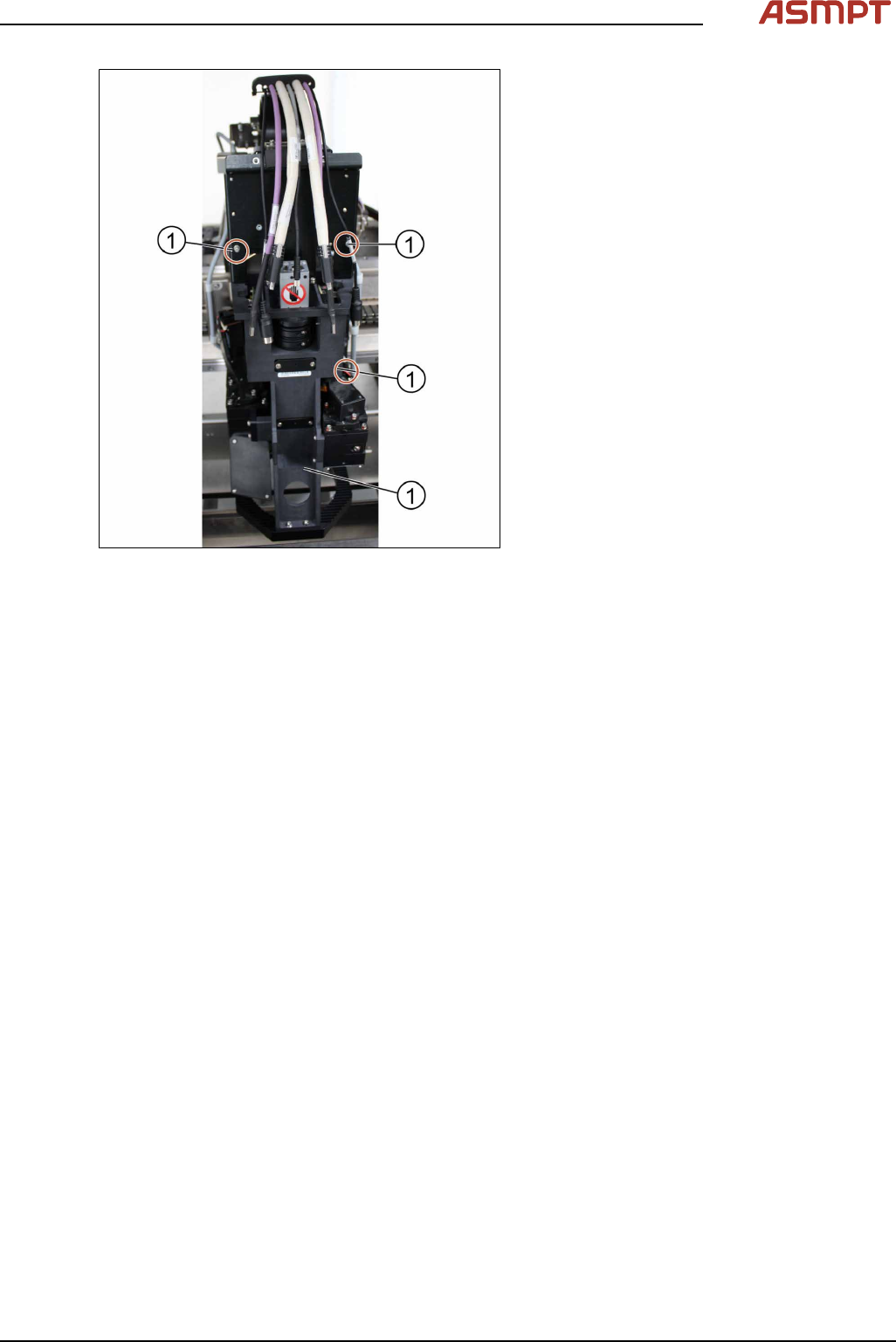
Fig.6: Removing the cable connectors
► Remove the two screws(1) mounted on
top of the optical head fixing the ribbon
cable connectors using an Allen key size
2.5.
► Remove the ribbon cable connectors out
of the sockets by pulling the clamps apart.
3 Replacing spare parts
Service Manual Process Lens PL - 03/2025 23
Fig.7: Removing the screws
► Remove the screws(1) fixing the optical
head at the machine using an Allen key
size 2.5. Start from the bottom.
► Carefully remove all screws. Make sure
you don’t drop the optical head.
► Remove the optical head.
Installation
Follow the removal instructions in reverse order for installation.
Check the calibration of the optical head
When the optical head is removed from the machine the optical head needs to be calibrated again.
See also 4.1 "Calibrations - 2D and 3D Calibrations" [}136].
3 Replacing spare parts
24 Service Manual Process Lens PL - 03/2025
3.1.1.2 Replacing the low ring light board
Parts
03122925-xx PCBA low ring light board
Equipment and tools
●
Allen key size 2.5
●
Philips screwdriver
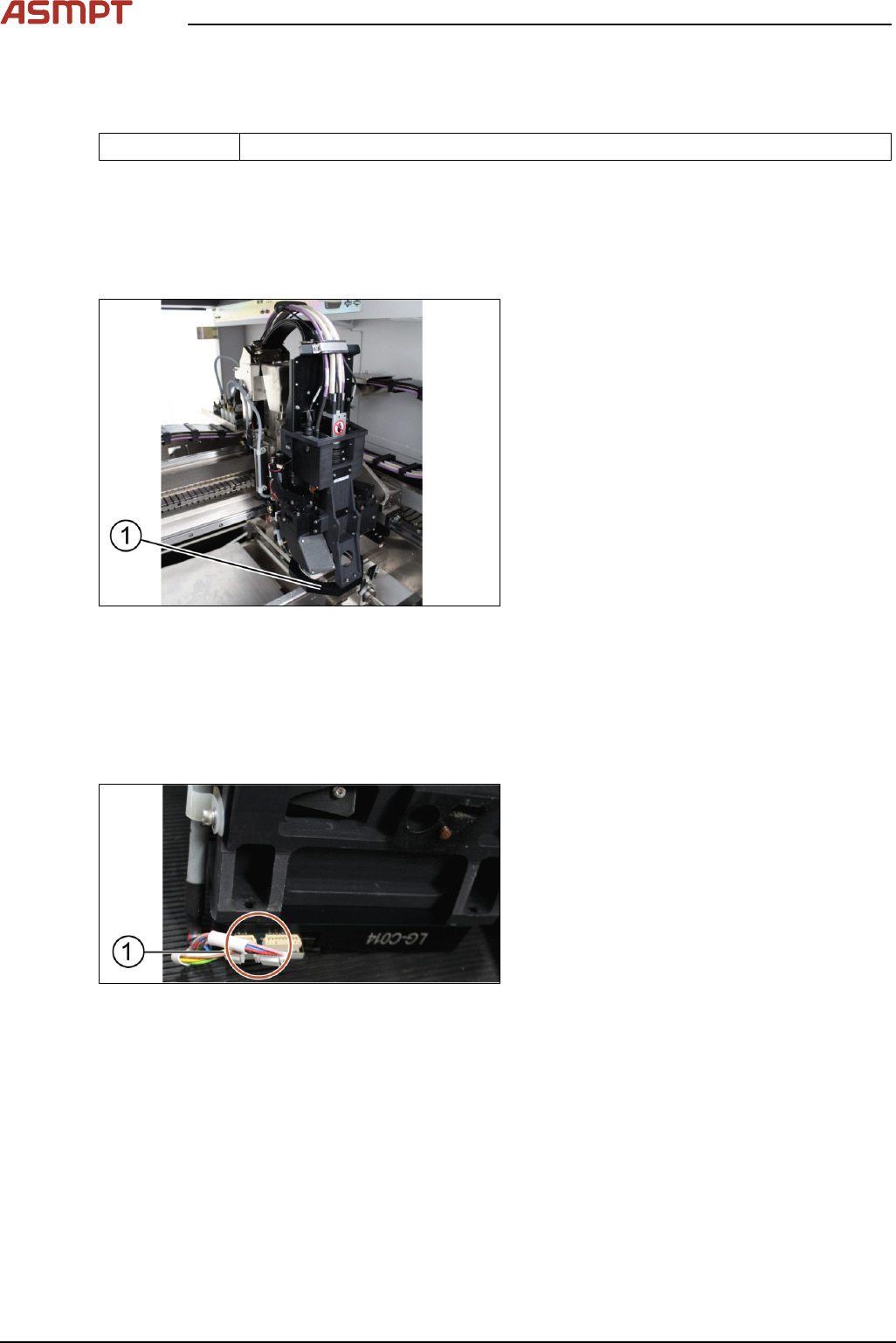
Overview
Fig.8: Low ring light assembly
1. Low ring light assembly
Requirements
●
Machine is switched off.
●
Use a T shaped Allen key to carry out this job.
Removal
Fig.9: Unplugging the connectors
► Unplug the connectors (1) at the back of
the low ring light assembly.