Process Lens PL Service Manual_EN.pdf - 第71页
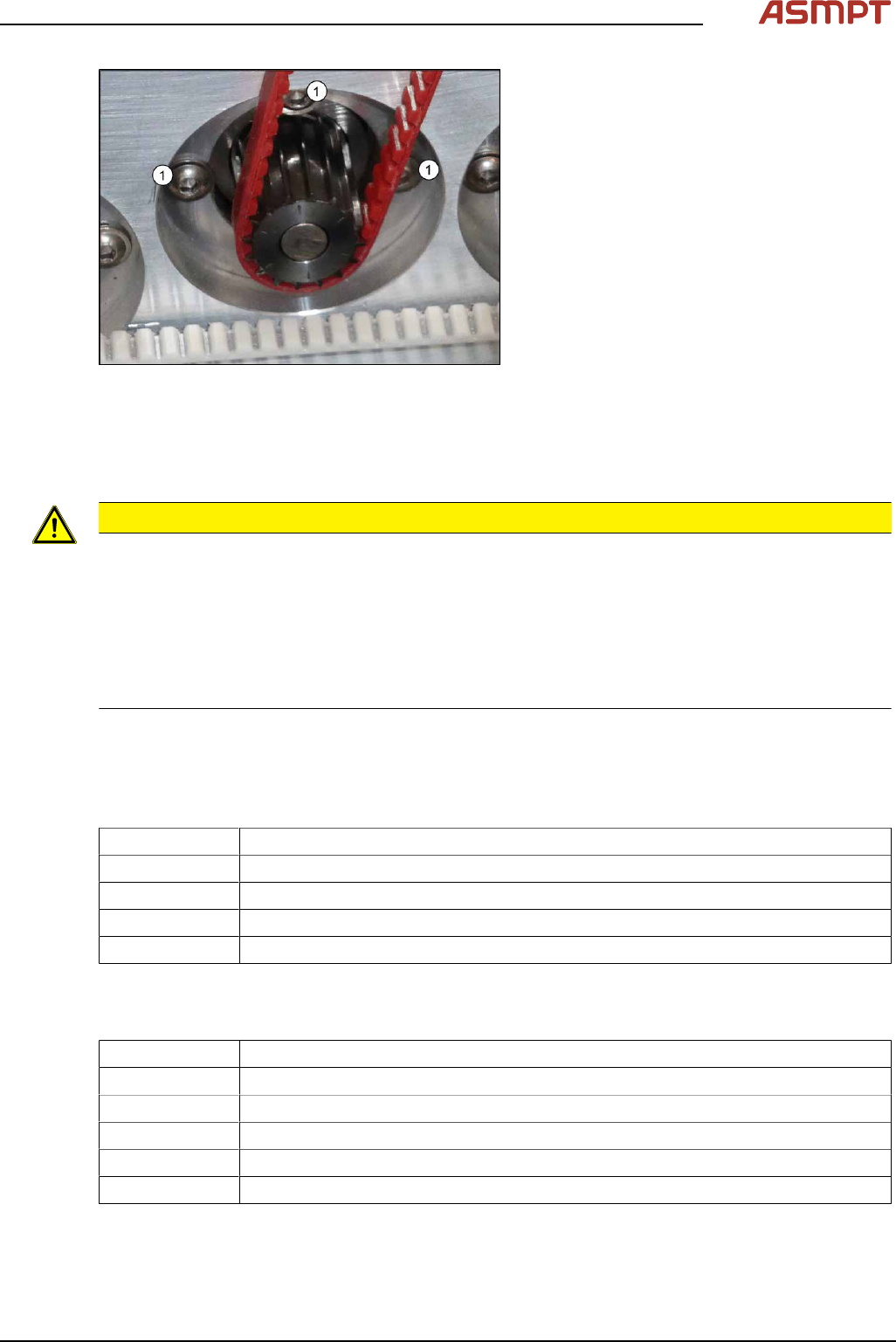
3 Replacing spare parts Se rv ic e Ma nu al P ro ce ss L en s PL - 0 3/ 20 25 71 Fig.93: Fastening screws ► Loosen the three screws (1) fastening the conveyor drive. ► Carefully unthread the toothed belt from the motor.…
3 Replacing spare parts
70 Service Manual Process Lens PL - 03/2025
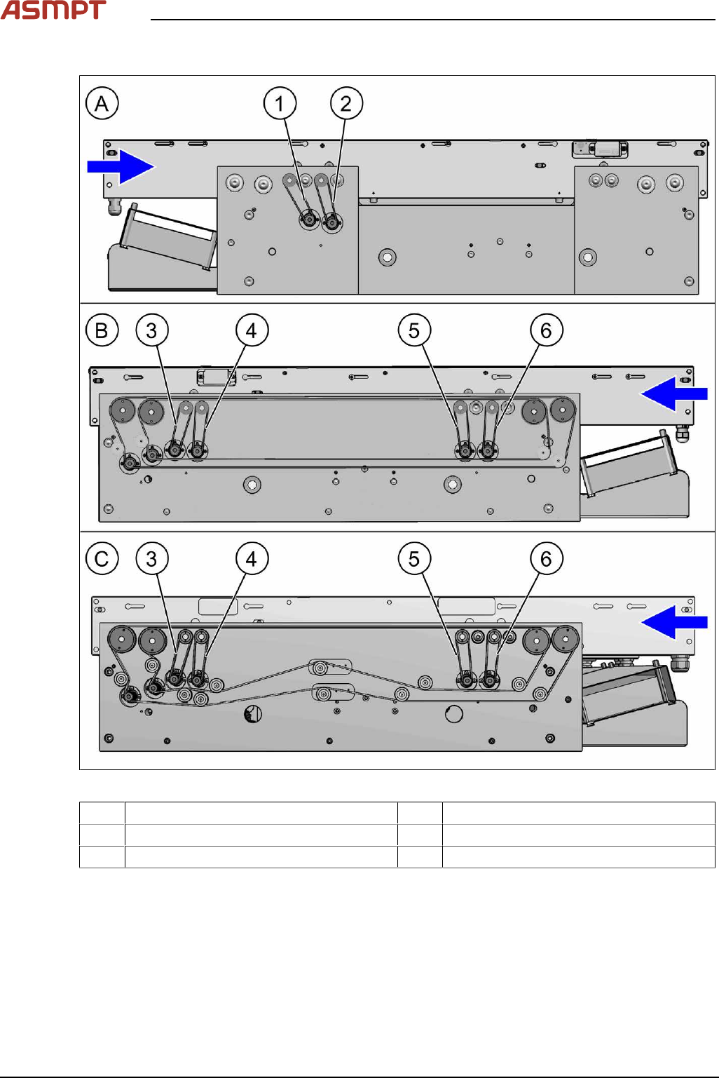
Overview
Fig.92: Overview of toothed belts (conveyor drives)
1 Toothed belt input conveyor track 1 2 Toothed belt placement area track 1
3 Toothed belt output area track 2 4 Toothed belt output area track 1
5 Toothed belt placement area track 2 6 Toothed belt input area track 2
See also: Replacing the conveyor drive
Removal
► Use the software or manually move the conveyor rail into a position which allows you best
access.
To move the conveyor side wall manually, pull the toothed belt of the width adjustment unit.
► Switch off the machine, disconnect it from the power supply and secure it to prevent unauthorized
reactivation.
► The fastening screws of the conveyor drives are on the outer side of the conveyor.
3 Replacing spare parts
Service Manual Process Lens PL - 03/2025 71
Fig.93: Fastening screws
► Loosen the three screws (1) fastening the
conveyor drive.
► Carefully unthread the toothed belt from
the motor.
Installation
► Follow the removal instructions in reverse order for installation. Also observe the following
instructions:
CAUTION
Installation instructions
► Make sure that the toothed belt is not folded or otherwise damaged.
► Make sure that the toothed belt is accurately positioned in the guidance on the motor shaft.
► Carefully thread in the toothed belt. To do this, carefully lift the toothed belt a little (e.g. with the
shorter end of an Allen key).
► Tighten the three screws fastening the conveyor drive hand-tight. At the same time, adjust the
belt tension to 210+/‑20Hz.
Replacing the cables (belt motor and width adjustment motor)
Parts
03113852-xx Sensor cable belt motor output track 1
03113854‑xx Motor cable width adjustment track 1
03113870-xx Motor cable belt motor output track 1
03113871‑xx Motor cable width adjustment track 1
03088836‑xx Cable CAN bus internal conveyor controller SX2
See also Replacing laser light barrier cables and fiber optic cables
Equipment and tools
02101037‑xx Loctite 241
00353832-xx Allen key set
00096290-xx Fork wrench set
00376503-xx Torx L-Wrench Set with Spherical head (Torx 30)
Side cutter
Cable tie
3 Replacing spare parts
72 Service Manual Process Lens PL - 03/2025
Removal
CAUTION
Do not loosen the wrong screws
Make sure that you do not loosen any other screws except those ones explicitly mentioned. Loosen-
ing other screws could lead to irreparable misalignment or damage to the conveyor.
► Use the software or manually move the conveyor rail into a position which allows you best
access.
To move the conveyor side wall manually, pull the toothed belt of the width adjustment unit.
► Switch off the machine, disconnect it from the power supply and secure it to prevent unauthorized
reactivation.
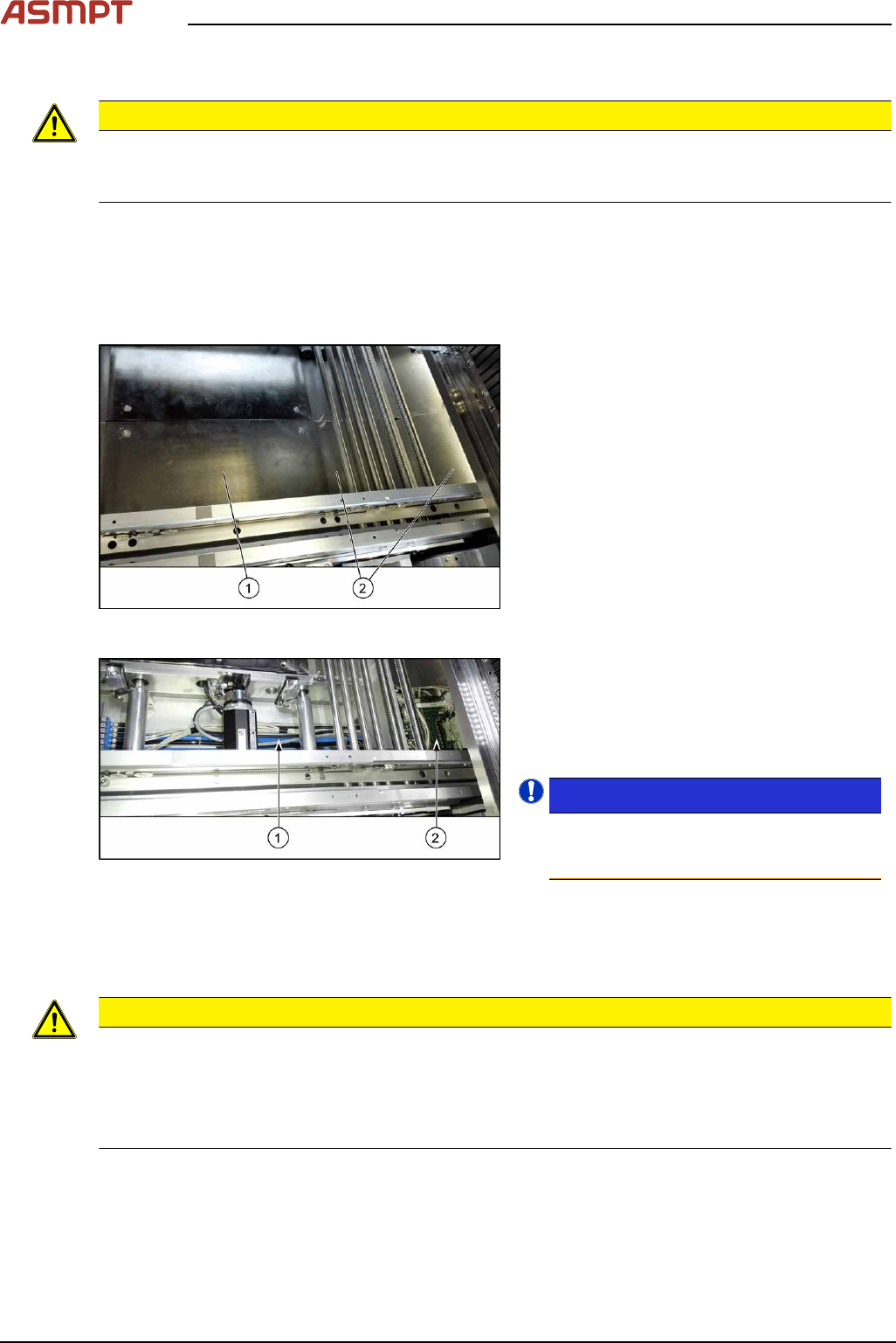
Fig.94: Table plate and covers
► Remove the four screws fastening the lift-
ing table plate(1) (see also Replacing the
Lifting Table Plate [03114873-xx]).
► Remove the fixing spacer bolts of the cov-
ers(2) above the conveyor control (two
screws each cover) and remove the cov-
ers.
Fig.95: Cables
The cables(1) run from the respective motor
over the floor of the conveyor to the conveyor
control(2).
► Carefully unthread the cables
Remove any cable ties.
NOTICE!
To have an overview of the cables refer to
Process Lens Circuit Diagram
[00900370‑xx].
.
Installation
► Follow the removal instructions in reverse order for installation. Also observe the following
instructions:
CAUTION
Installation instructions
► Observe the installation instructions for the conveyor drive where necessary.
► Replace any open cable ties.
Make sure that the cable ties and the heads of the cable ties do not rub against any parts when
you do this.