Process Lens PL Service Manual_EN.pdf - 第76页
3 Replacing spare parts 76 Se rv ic e Ma nu al P ro ce ss L en s PL - 0 3/ 20 25 Fig.100: Idler pulley ► Remove the fastening screw of the idler pulley (1) and take the idler pulley off. Installation ► Fasten the idler…
3 Replacing spare parts
Service Manual Process Lens PL - 03/2025 75
Equipment and tools
00386253‑xx Torque screwdriver ESD 0.4 - 1.0Nm
03078706‑xx Bit holder for screwdriver TorqueVario
Bit, size 4
00326015‑xx Belt tension measuring device
If required:
Magnet lifter or tweezers and adhesive tape
Measuring scale
Overview
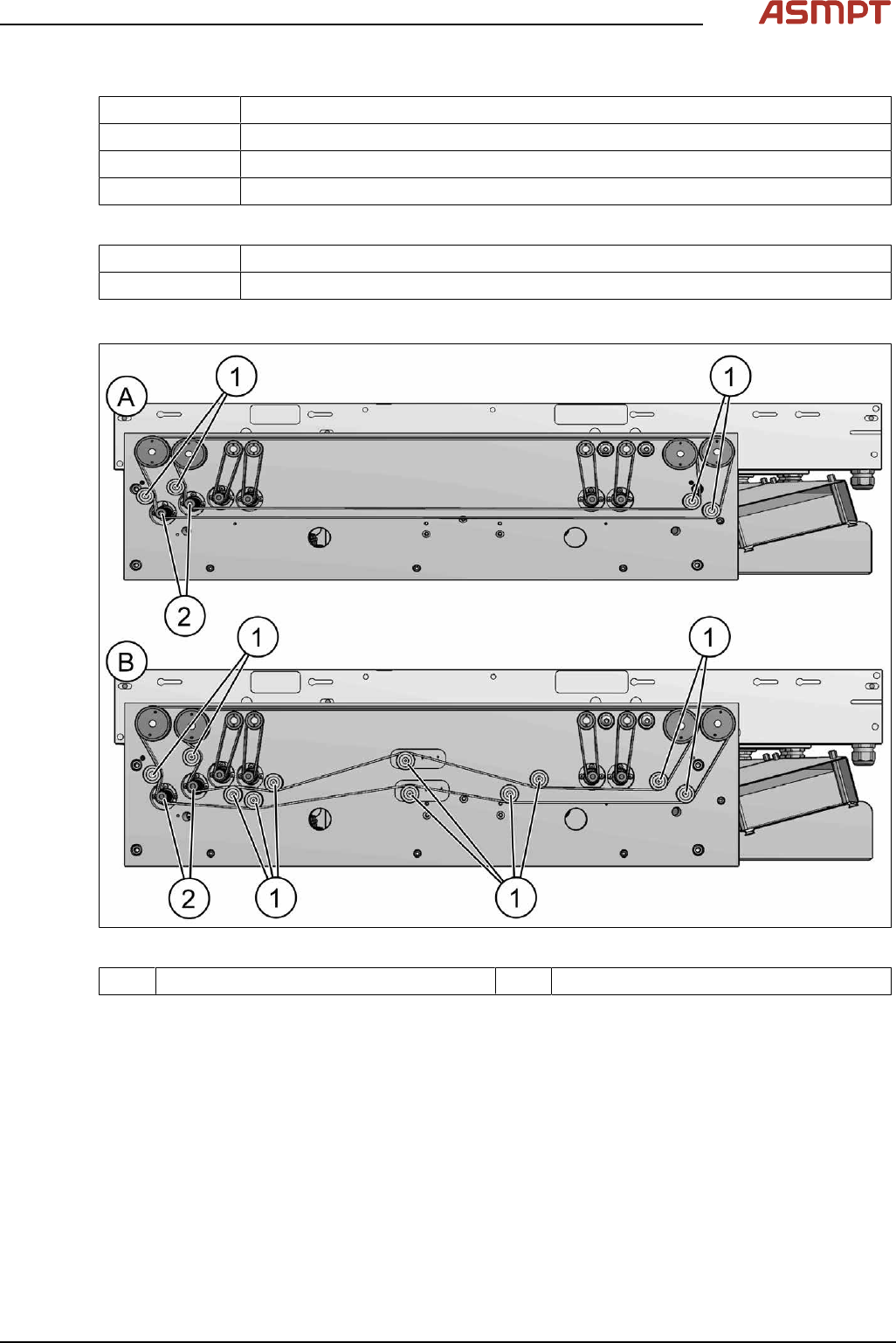
Fig.99: Overview of idler pulleys (width adjustement)
1 Deflection pulleys 2 Width adjustment motor
Removal
► Switch off the machine, disconnect it from the power supply and secure it to prevent unauthorized
reactivation.
► Loosen the toothed belt (width adjustment).
Replacing the toothed belt (width adjustment)
3 Replacing spare parts
76 Service Manual Process Lens PL - 03/2025
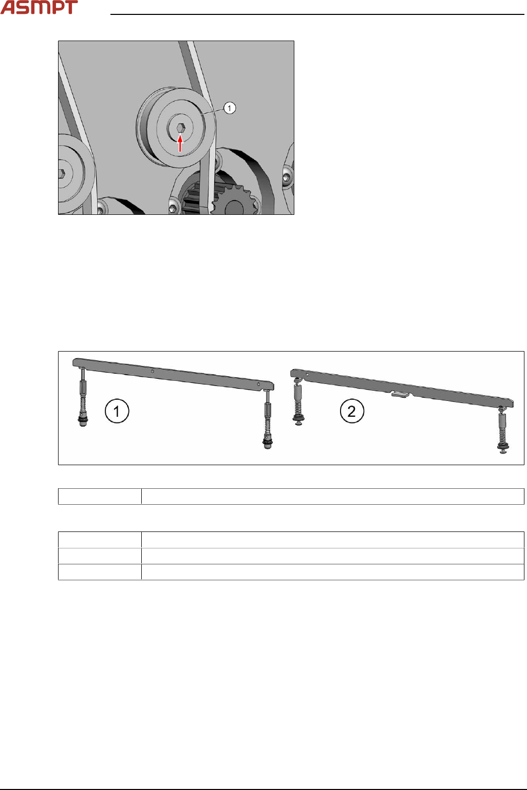
Fig.100: Idler pulley
► Remove the fastening screw of the idler
pulley(1) and take the idler pulley off.
Installation
► Fasten the idler pulley with a screw.
► For further installation, proceed as described in section Replacing the toothed belt (width adjust-
ment).
Replacing the clamping unit
Parts
Fig.101: Clamping unit
03121328-xx Clamping unit 4 complete M-C
Equipment and tools
02101037‑xx Loctite 241
00353832-xx Allen key set
00376503-xx Torx L-Wrench Set with Spherical head (Torx 30)

3 Replacing spare parts
Service Manual Process Lens PL - 03/2025 77
Overview
Fig.102: Clamping unit
1. Clamping unit on conveyor rail
2. Clamping unit complete
3. actuator
Removal
CAUTION
Small parts
► Take care not to lose any small parts.
► Take particular care not to let the screws fall into the conveyor rail when removing the screws or
clamping plate.
► Use the software or manually move the conveyor rail into a position which allows you best
access.
To move the conveyor side wall manually, pull the toothed belt of the width adjustment unit.
► Switch off the machine, disconnect it from the power supply and secure it to prevent unauthorized
reactivation.
► Remove the lifting table plate to make room for removing the actuator later (see chapter Repla-
cing the Lifting Table Plate [03114873-xx]).