Process Lens PL Service Manual_EN.pdf - 第60页
3 Replacing spare parts 60 Se rv ic e Ma nu al P ro ce ss L en s PL - 0 3/ 20 25 Equipment and tools 00376503-xx Torx L-Wrench Set with Spherical head (Torx 30) Overview Fig.75: Plate guide 1. Plate guide 1 2. Plate gui…
3 Replacing spare parts
Service Manual Process Lens PL - 03/2025 59
► Remove the screws fastening the lifting table plate and remove the lifting table plate from the
machine. The lifting table plate is pinned to the table plate guides but can be easily pulled off.
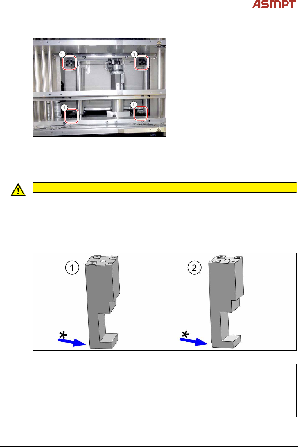
Fig.73: Plate guides
► Mark the positions of the table plate
guides(1) to make it easier to refit them
later on.
Make sure you do not confuse these. If
you do, you will need to reset the parallel-
ism of the lifting table plates.
Installation
► Follow the removal instructions in reverse order for installation. Also observe the following
instructions:
CAUTION
Installation instructions
► Place the lifting table plate onto the guidance pins. Make sure that the fastening screws slide
properly into the precut thread.
► Check the free movement of the lifting table (see Checking free movement of lifting table).
Replacing the plate guides
Parts
Fig.74: Plate guide
03119681‑xx Plate guide RC
03119681Sxx Plate guide RC (spare parts kit)
Includes:
●
Plate guide RC [03119681‑xx]
●
Self-cutting screw REMFORM RF-SN85-6 x 20-9.8 [03034122‑xx]
●
2x pin ISO 8734 - 3 x 12 - A-ST [03015751‑xx]
3 Replacing spare parts
60 Service Manual Process Lens PL - 03/2025
Equipment and tools
00376503-xx Torx L-Wrench Set with Spherical head (Torx 30)
Overview
Fig.75: Plate guide
1. Plate guide 1
2. Plate guide 2
3. Pins
4. Self-cutting screw
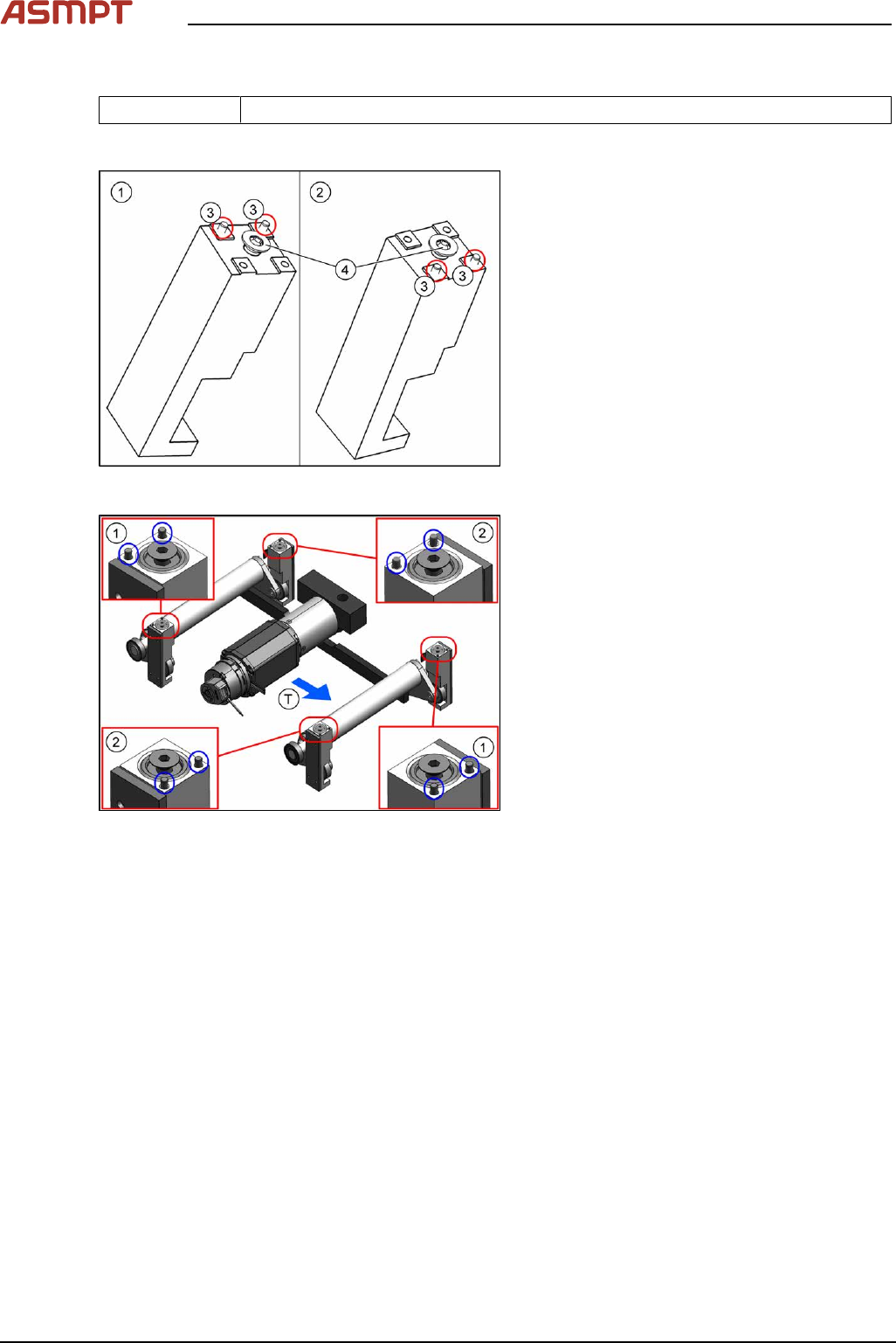
Fig.76: Pins on the plate guides
1. Plate guide 1
2. Plate guide 2
TTransport direction
Removal
► Use the software or manually move the conveyor rail into a position which allows you best
access.
To move the conveyor side wall manually, pull the toothed belt of the width adjustment unit.
► Switch off the machine, disconnect it from the power supply and secure it to prevent unauthorized
reactivation.
► Dismantle the lifting table plate (see 3.5.1.2.1 "Replacing the lifting table plate" [}58]).
3 Replacing spare parts
Service Manual Process Lens PL - 03/2025 61
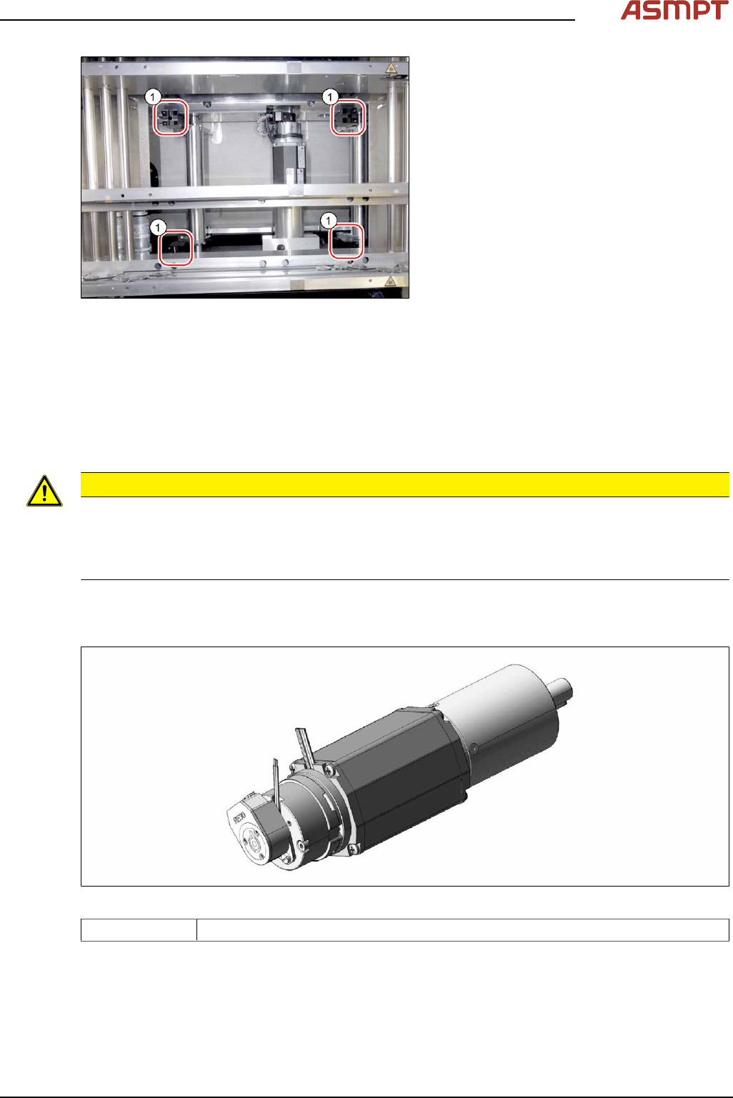
Fig.77: Plate guides
► Remove the relevant plate guide(1).
Installation
► Press in the two pins at the plate guide. Consider the right position depending on the position in
the lifting table. The pins are always on the outside position of the table.
► Insert the self-cutting screw in the center. You can precut the hole with this screw.
► Follow the removal instructions in reverse order for further installation. Also observe the following
instructions:
CAUTION
Installation instructions
► Place the lifting table plate onto the guidance pins. Make sure that the fastening screws slide
properly into the precut thread.
► Check the free movement of the lifting table (see Checking free movement of lifting table).
Replacing the lifting table motor
Parts
Fig.78: Lifting Table Motor
03088241-xx BLDC motor BG65x50 complete with cable and plug