Process Lens PL Service Manual_EN.pdf - 第155页
4 Machine - Calibrations Se rv ic e Ma nu al P ro ce ss L en s PL - 0 3/ 20 25 15 5 ► Lower the conveyor lift cable. ► Open the machine cover. ► Remove the mapping plate. ► Uninstall the coaxial light. ► Reconnect the Lo…
4 Machine - Calibrations
154 Service Manual Process Lens PL - 03/2025
Step 5
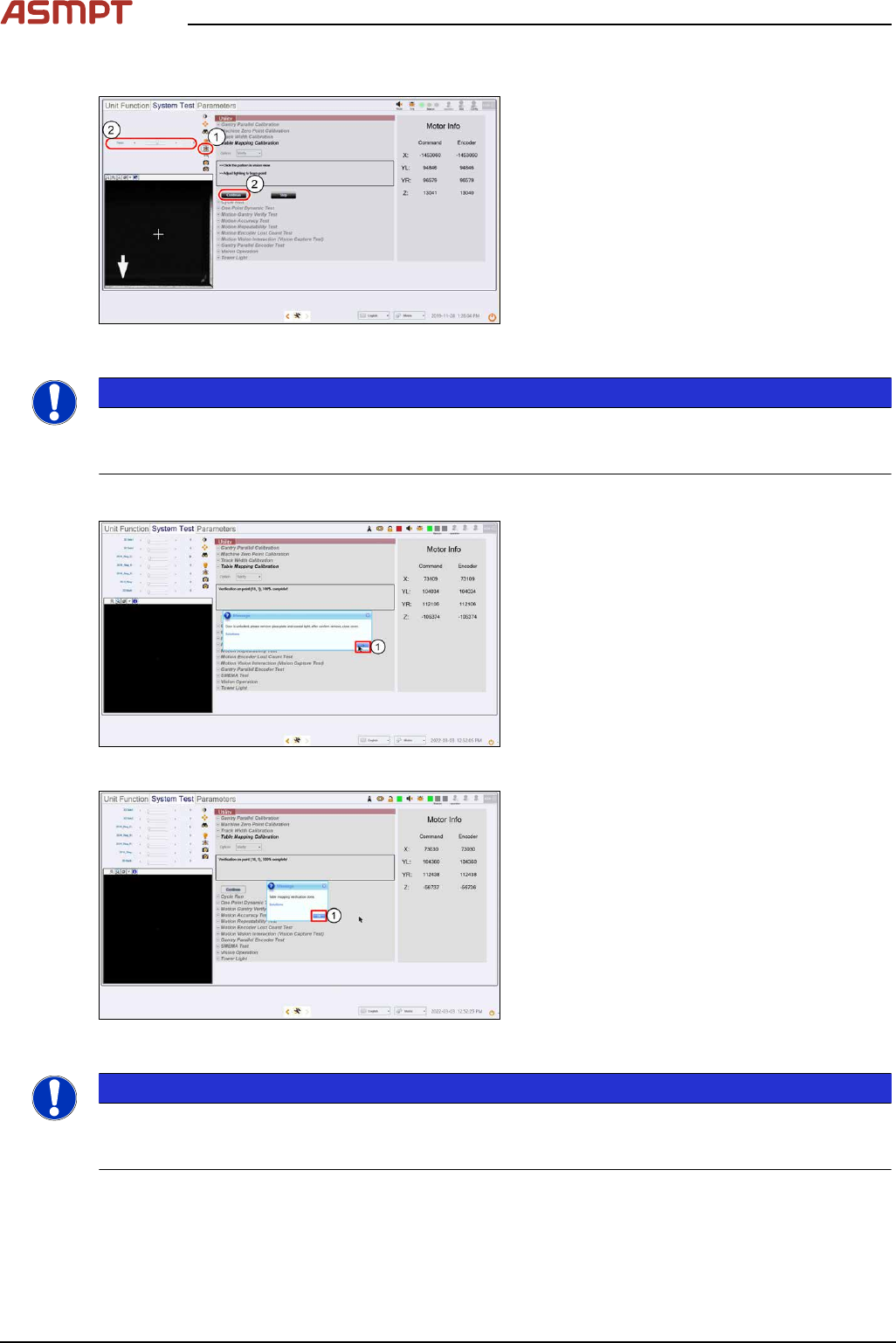
Fig.238: “Focus” icon
► Click on Focus icon (1).
► Adjust Focus (2) between 50 ~ 60.
► Click Continue (3) to start the teach table
mapping process.
The progress of the mapping is continu-
ously reported.
NOTICE
At 50% completion, the table towers, the stopper rises, and the plate will move forward to the stopper
to continue the second stage of the mapping. Do not be alarmed by this sudden movement. No user
intervention is required.
Step 6
Fig.239: Message”
► A message pops up asking for the removal
of the coaxial light and mapping plate.
Click Ok (1) once completed.
Fig.240: Message
► A successful verification is completed.
Click Ok (1).
NOTICE
If the mapping fails, clean the plate and repeat the procedure. Mapping failures are caused by a fail-
ure to read a fiducial on the plate – usually caused by fingerprint smudges on the fiducials. Verifica-
tion of the mapping results is necessary after a successful Teach.
4 Machine - Calibrations
Service Manual Process Lens PL - 03/2025 155
► Lower the conveyor lift cable.
► Open the machine cover.
► Remove the mapping plate.
► Uninstall the coaxial light.
► Reconnect the Low Ring light connector.
► Open the machine cover.
NOTICE
The mapping information is stored in C:\system\Log\TableMapping_timestamp*.log file (approx.
459KB).
The Delta of Gantry to fiducials` positions should be ≤ 20µm (0.020mm).
4.5 Calibrations – FOV Height Calibration
What is FOV Height Calibration?
This procedure is a Type 1 Gauge study to determine the Process Lens PL as a measurement system
is capable of measuring parts consistently and accurately.
What is Cg & Cgk?
Cg compares the known tolerance with measurement variation, while Cgk compares the known toler-
ance with both measurement variation and bias. Large Cg and Cgk indicate the variation due to the
measurement system is small compared with the tolerance range. A typical threshold for both these
values is 1.33 (i.e. the Process Lens PL performance is acceptable only if the Cg and Cgk exceeds
1.33).
Target Height Reference
The target height reference serves as a point of comparison in the study. It is determined by averaging
multiple measurements by the Process Lens PL against the target that was measured with measuring
equipment of higher level of accuracy and precision (the "golden unit" of reference). Ideally, the height
measured should be close to the center of the height's tolerance zone.
●
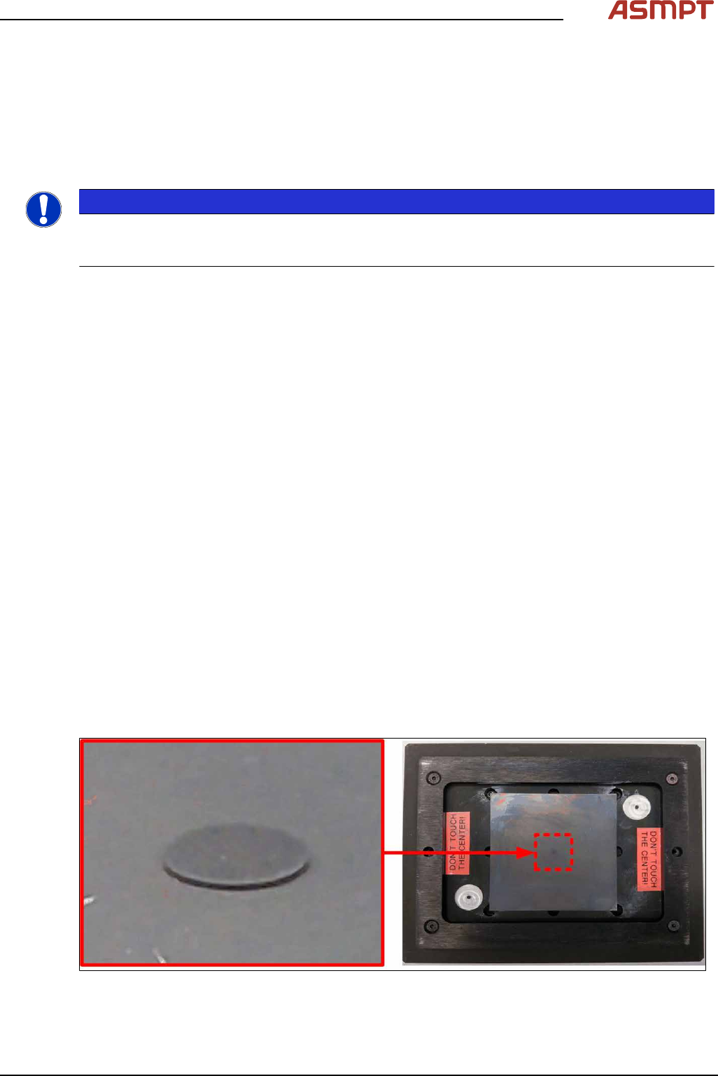
The target is a Diameter 2mm cylindrical disc of nominal design height 120±6µm.
●
Refer to the certificate that comes with the target for the certified height.
Handling Caution
●
Fragile! Handle with care. The target is made from high precision ceramic.
●
Touching the target will contaminate the target with debris (sebum oil and human skin) which will
severely distort measurements.
Magnified side view of the height target. The tar-
get is a raised disc against a flat substrate.
Certified glass height target in fixture.
4 Machine - Calibrations
156 Service Manual Process Lens PL - 03/2025
Target Information
Mechanical feature Dimension Mechanical feature Dimension
Fixture overall length 155mm Target shape Circle
Fixture overall width 122mm Target diameter 2mm
Fixture edge thickness 4mm Target thickness 123µm (in the range
of 120µm)
Target area (standard):
H15
HD10/HD20
4mm x 4mm
6mm x 6mm
WARNING
DO NOT TOUCH THE TARGET
Maintain the target area free from dirt and contamination.
Teach and Verify Sequences:
The camera moves over the target and captures the target at 9 different positions of the FOV (Field of
View). In each FOV position, the camera measures the Golden target 50 times to determine the aver-
age value, calibrate the height measurements across the FOV, and determine the repeatability for
each position.
Before running this calibration it is assumed:
●
The 2D and 3D calibration procedure is performed again. See calibration flow.
●
Correct top.dev file is installed.
Run times:
●
The calibration run will take approximately 18 minutes.
●
The verification run will take approximately 15 minutes
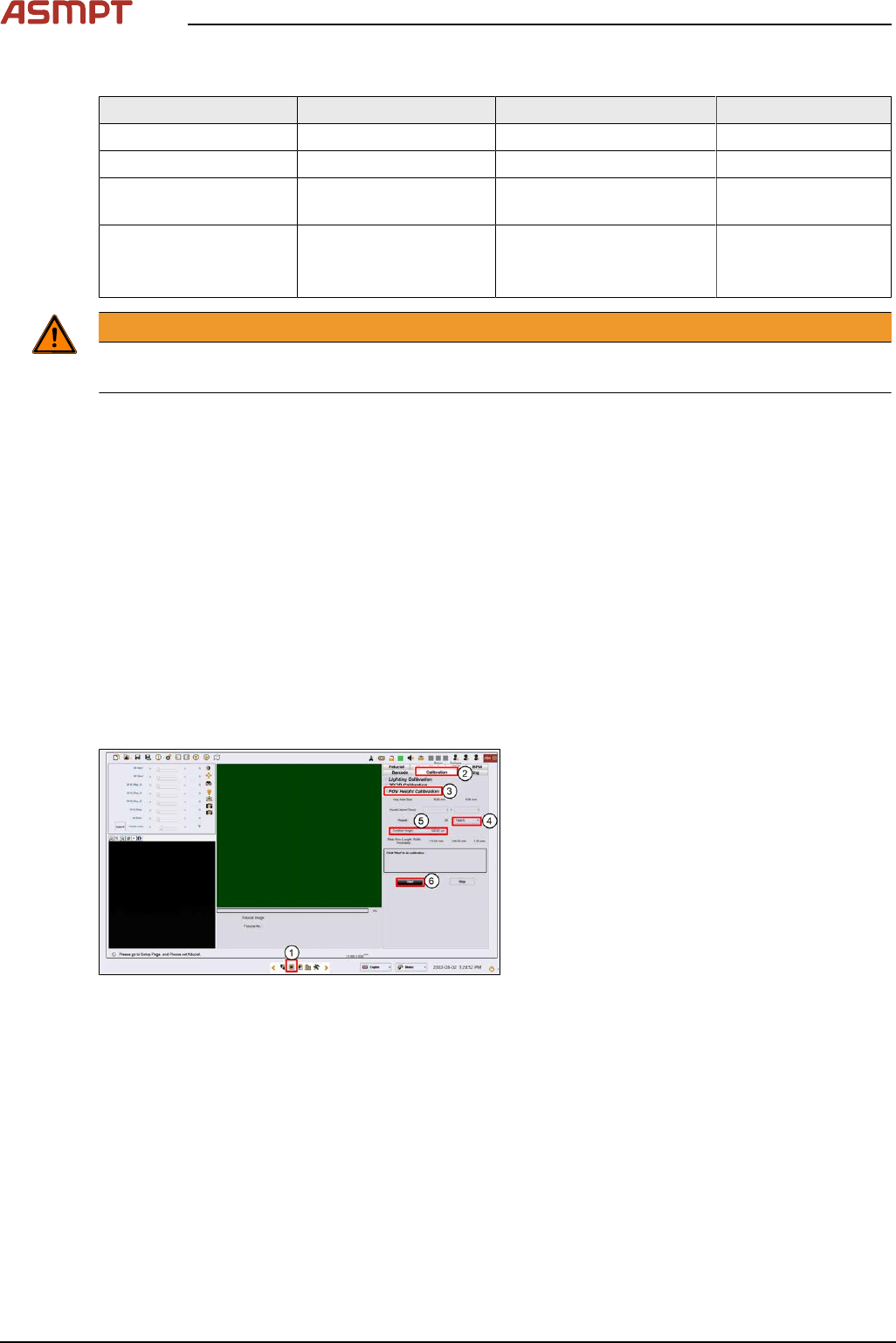
Step 1
Fig.241: Vision page
► Click on the Vision page(1).
► Click on Calibration(2).
► Click on FOV Height Calibration(3).
► Select Teach(4).