Process Lens PL Service Manual_EN.pdf - 第49页
3 Replacing spare parts Se rv ic e Ma nu al P ro ce ss L en s PL - 0 3/ 20 25 49 3.2.2.2 Checking the DLP connection In the device manager, we should see two devices as “DLPGTwo_Device”, that means both side of the DLP a…
3 Replacing spare parts
48 Service Manual Process Lens PL - 03/2025
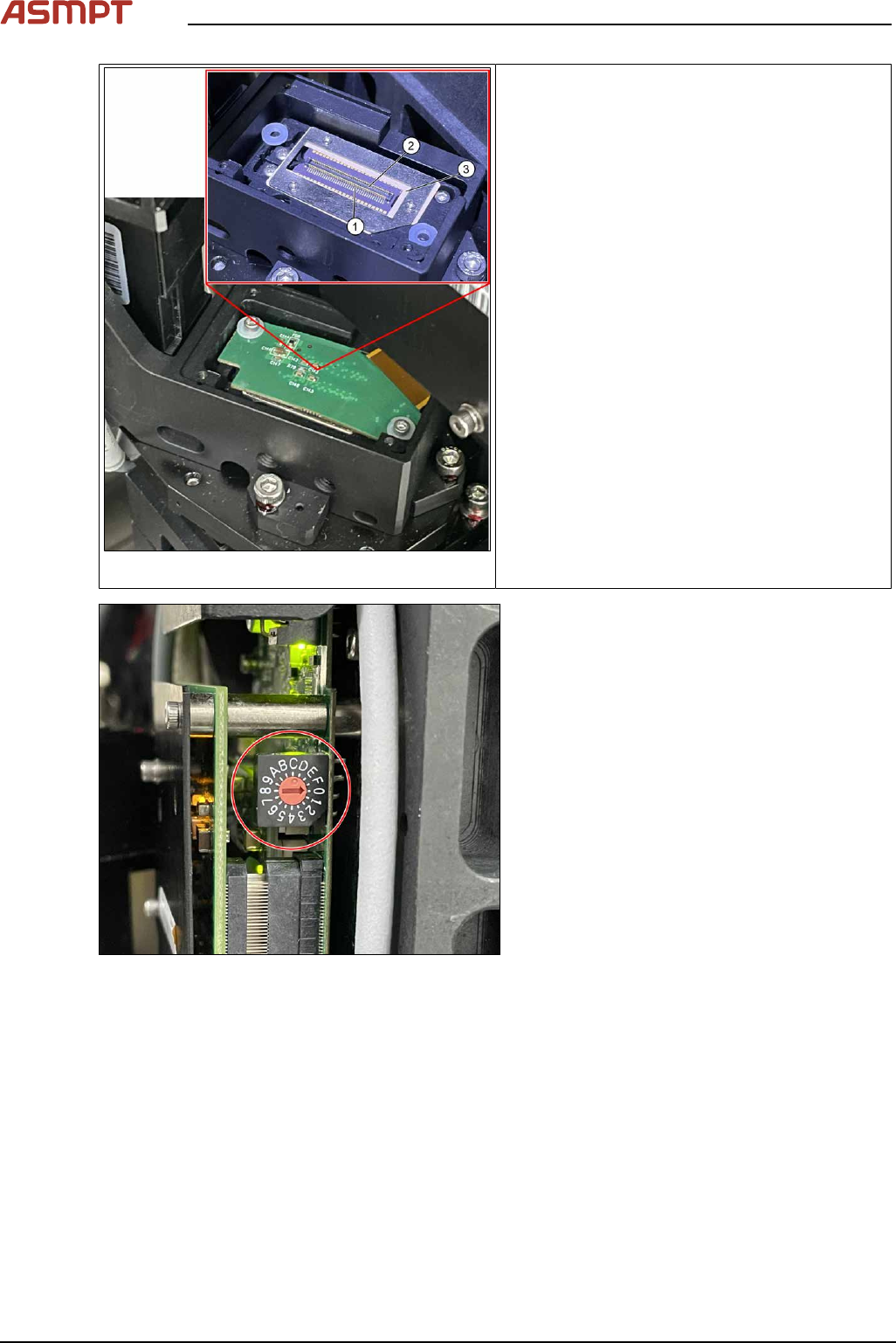
Fig.54: Alignment
1. Pin
2. Connector
3. DMD to DLP Controller
ü DLP module is dismantled.
► Put the DLP module in its position.
► Make sure that the connector is in the right
position and doesn’t bend the pin. Use an
external light to check that the holes of the
connector and the drilling holes for the
screws are in line.
Fig.55: Setting controller ID
► Set DLP controller ID.
Left side DLP controller should be configured
as 0, right side DLP controller should be con-
figured as 1.
Check the calibration of the optical head
When the DLP Controller is removed from the optical head, calibration is to be calibrated again. Refer
to chapter "4 Machine - Calibrations".
3 Replacing spare parts
Service Manual Process Lens PL - 03/2025 49
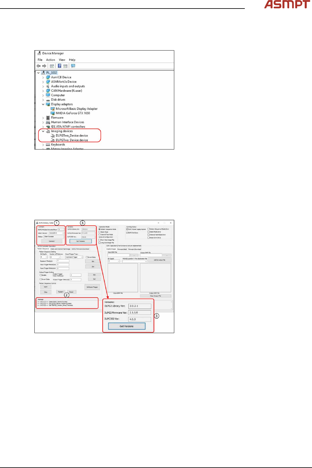
3.2.2.2 Checking the DLP connection
In the device manager, we should see two devices as “DLPGTwo_Device”, that means both side of
the DLP are connected.
Fig.56: Checking the Device Manager
► Open Device Manager.
► Check if Device Manager displays two
Imaging devices.
3.2.2.3 Checking the connection and firmware version of the DLP module
When the DLP module and the DMD module have been changed, a software check for the latest Ver-
sion is needed.
Requirements
●
Machine is switched on.
Fig.57: Checking connection and firmware
► Open DLPG2Library_Tester.exe
► Select ModuleID:=0 for Select Device,
press Connect (1).
► Check that the connection is successful,
i.e. status becomes open success and
Message box (2) shows Open DLPG2
Device Success.
► Press Get Version (3) to obtain version
numbers.
► Compare version numbers with the follow-
ing. If not the same, please contact with
the engineers in charge (mentioned in IN-
TRODUCTION section).
Repeat steps with ModuleID:=1.
3 Replacing spare parts
50 Service Manual Process Lens PL - 03/2025
3.3 Encoder
3.3.1 Replacing the encoder reader at the x, y and z gantry
Parts for Process Lens PL
03122960-xx Tonic encoder interface 0.1UM
(Encoder reader X, Y, Z)
Parts for Process Lens PL Single-Lane
03157187-xx X Encoder Assy
03157188-xx Y Gantry Left Encoder Assy
03157190-xx Y Gantry Right Encoder Assy
03153580-xx Z axis encoder
Equipment and tools
●
Allen key size 2.0
●
Spacer 2.1mm
Requirements
●
Machine is switched off.
Removal and Installation
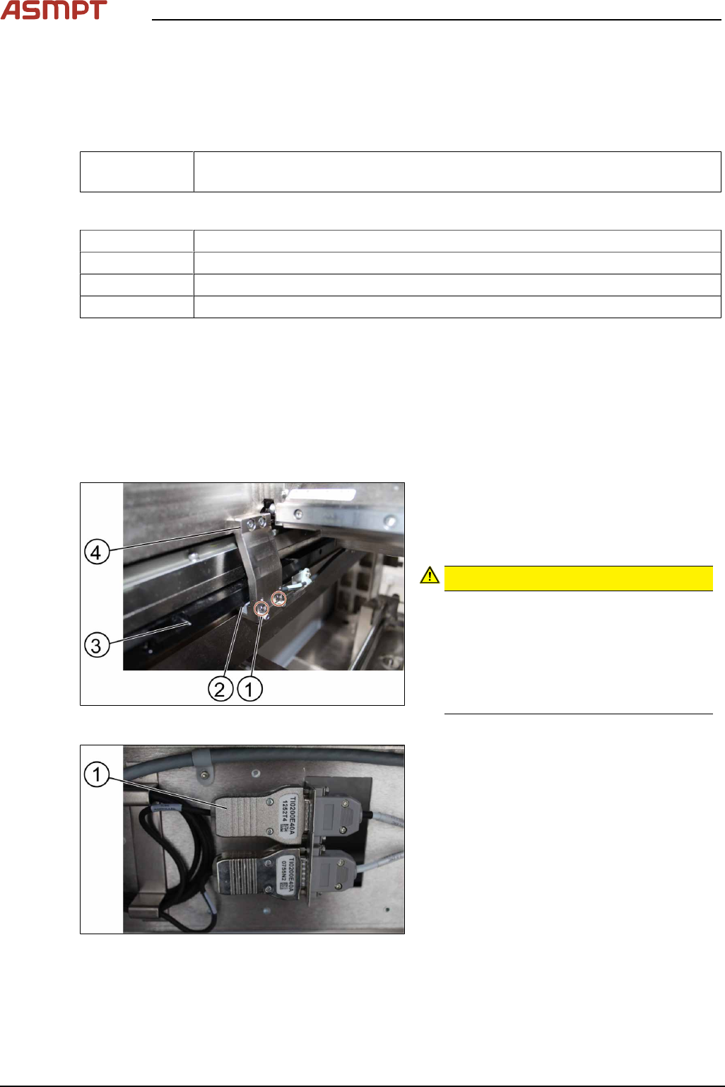
Fig.58: Removing the screws
► Remove the two screws(1) using an Allen
T shaped Allen key size 2.0.
► Carefully pull out the encoder reader(2).
The scale of the scale bars
CAUTION!
Fingerprints or scratches damage the
scale bars(3) which then need to be
exchanged.
Do not touch or scratch the scale of the
scale bars.
Be careful when pulling out the reader
and when putting it back again.
.
Fig.59: Changing the reader
► Change the reader including the en-
coder(1) and all cables.
► Replace the encoder and the reader.