Process Lens PL Service Manual_EN.pdf - 第131页
3 Replacing spare parts Se rv ic e Ma nu al P ro ce ss L en s PL - 0 3/ 20 25 13 1 3.5.2.7 Changing the TSP400 Removing the TSP400 Fig.187: TSP400 1. TSP400 Parts 03060811-xx Conveyor controller TSP-400 CPL Equipment an…
3 Replacing spare parts
130 Service Manual Process Lens PL - 03/2025
Changing the sensors of the stopper and sensors rail
Parts
03122931-xx SPI conveyor input area SNR (Input sensor)
03122932-xx Conveyor sonar sensor cable (Sonar sensor)
03122933-xx SPI conveyor output area SNR cable (Output sensor)
Equipment and tools
●
Allen key size 2.0
Key:
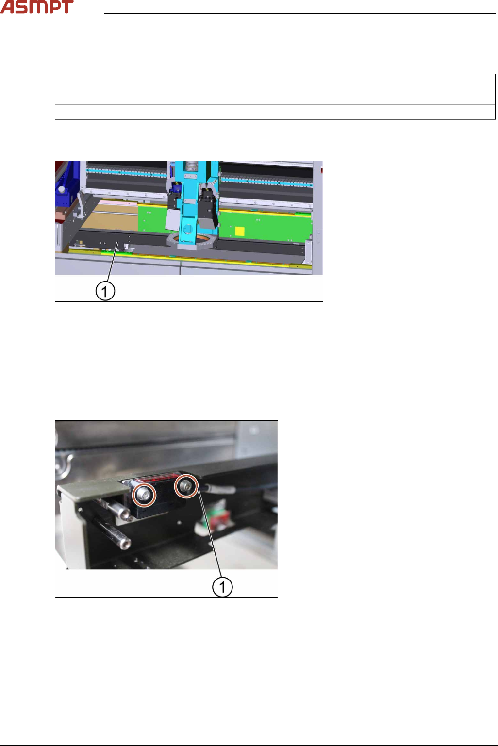
1. Stopper and sensors rail
Figure 3‑61: Stopper unit
Requirement:
●
Machine is switched off.
► Remove the cover of the stopper and sensors rail by unscrewing 10 x screws using an Allen key
size 2.0 (small screws).
► Furthermore unscrew 4 x screws using an Allen key size 2.5 (large screws).
► The cover is removed.
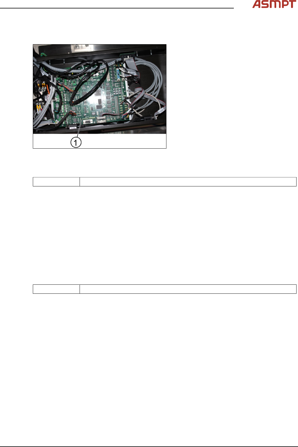
Key:
1. Screw (2 x)
Figure 3‑62: Sensor
► Unscrew the screws to remove the input sensor, sonar sensor or output senor using an Allen key
size 2.0.
► Change the sensors and tighten the screws (2 x).
► Put the cover back onto the stopper and sensors rail and tighten the screws (14 x).
Installation
Follow the removal instructions in reverse order for installation.
3 Replacing spare parts
Service Manual Process Lens PL - 03/2025 131
3.5.2.7 Changing the TSP400
Removing the TSP400
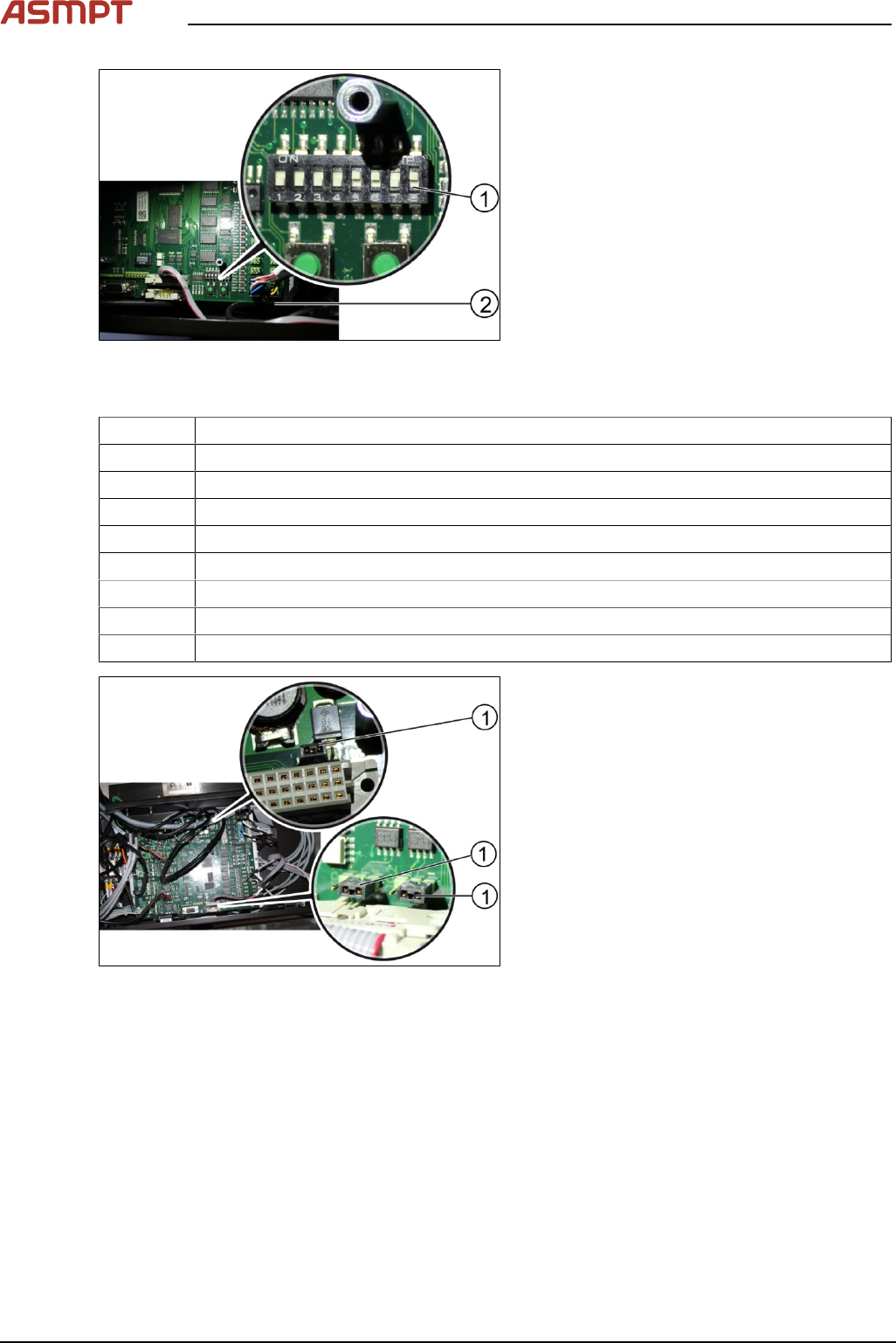
Fig.187: TSP400
1. TSP400
Parts
03060811-xx Conveyor controller TSP-400 CPL
Equipment and tools
●
Allen key size 2.5
Requirements
●
Machine is switched off.
► Disconnect all connectors of the board.
► Unscrew all screws (16) using an T shaped Allen key size 2.5.
► Remove the circuit board.
Replacing the TSP400
Parts
03060811-xx Conveyor controller TSP-400 CPL
Equipment and tools
●
Allen key size 2.5
Requirements
●
Machine is switched off.
●
TSP400 is dismantled.
► Place the new TSP400 into the box.
► Tighten the screws (16 x).
3 Replacing spare parts
132 Service Manual Process Lens PL - 03/2025
Fig.188: Switches
1. Switches
2. TSP400
► Check whether the switches on the circuit board are in the right "ON" or "OFF" position.
Number Position of the switch (ON/OFF)
1 OFF
2 OFF
3 OFF
4 OFF
5 ON
6 ON
7 OFF
8 ON
Fig.189: Jumpers at TSP400
► Check that the jumpers(1) are in place as
shown in the picture above.