Process Lens PL Service Manual_EN.pdf - 第94页
3 Replacing spare parts 94 Se rv ic e Ma nu al P ro ce ss L en s PL - 0 3/ 20 25 Correcting the laser light barrier setting DANGER Laser Class 2 The laser light barrier transmitter emits class 2 laser beams. You therefor…
3 Replacing spare parts
Service Manual Process Lens PL - 03/2025 93
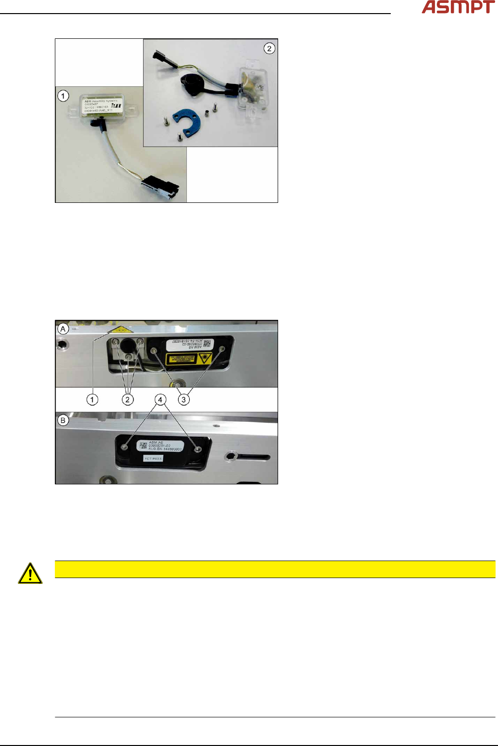
Fig.126: Transmitter and receiver
1. Receiver
2. Transmitter (incl. assembly material)
Removal
► Use the software or manually move the conveyor rail into a position which allows you best
access.
To move the conveyor side wall manually, pull the toothed belt of the width adjustment unit.
► Switch off the machine, disconnect it from the power supply and secure it to prevent unauthorized
reactivation.
Fig.127: Removing transmitter and receiver
The transmitters are always near the laser
warning labels(1). The receivers are always on
the opposite rails.
► (A) Transmitter:
Remove the five fastening screws(2)
and(3). Make sure that no parts fall into
the conveyor rail.
► (B) Receiver:
Remove the two fastening screws(4).
Make sure that no parts fall into the con-
veyor rail.
► Unplug the electrical connection.
Installation
► Follow the removal instructions in reverse order for installation. Also observe the following
instructions:
CAUTION
Installation instructions
► Reconnect the transmitter/receiver before installation.
► Make sure that all the other cables in the conveyor rail are run under the transmitter/receiver.
There is a particular lack of space at the transmitters.
► Use the bushing for the bottom screw. This screw is used to fix the sensor.
The two upper screws are used to adjust the laser beam.
► The transmitters are fixed hand-tight with the lower screw and adjusted with the top two screws.
► Check the setting for the transmitter / receiver and correct it if necessary (see 3.5.1.6.4.1 "Setting
the fiber optic sensor" [}101]).
► Teach the PCB sensors using the station software (see Teaching the PCB sensors (SW70x)).
3 Replacing spare parts
94 Service Manual Process Lens PL - 03/2025
Correcting the laser light barrier setting
DANGER
Laser Class 2
The laser light barrier transmitter emits class 2 laser beams. You therefore do not require additional
protective measures!
► However, you should never look into the laser beam.
► Adjust the laser beam only from the rear side of the laser!
Equipment and tools
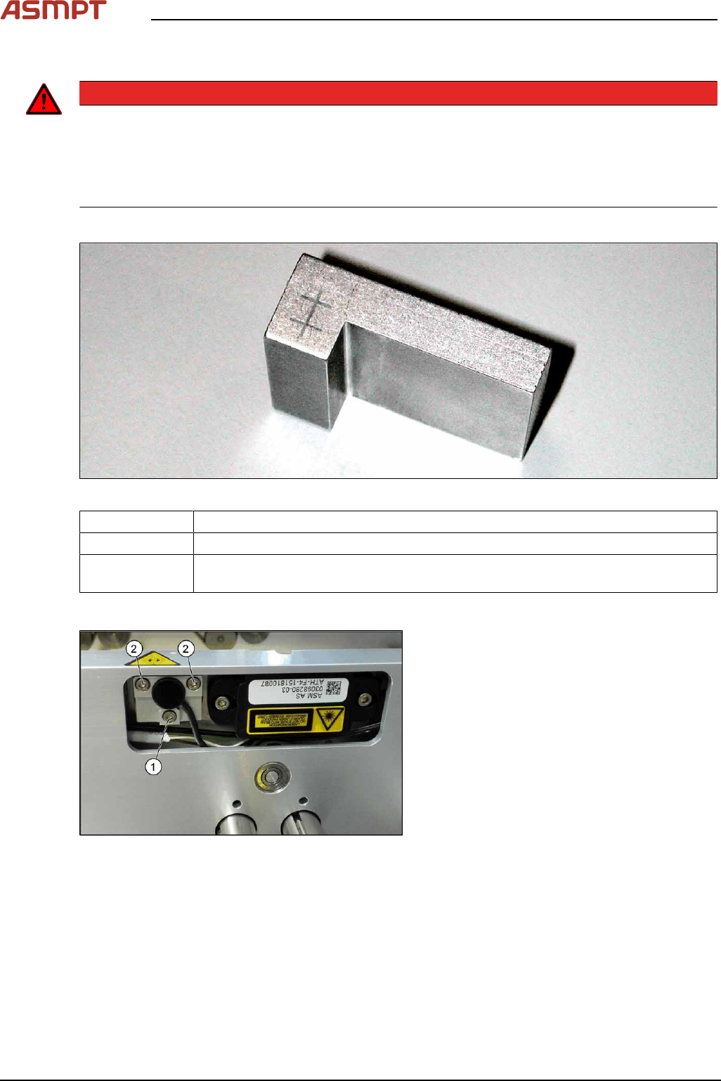
Fig.128: Setting gauge
00369205-xx Setting gauge for conveyor laser light barrier (optional)
00353832-xx Allen key set
Semi-transparent paper or plastic (recommendation for better recognition of the
laser beam)
Overview
Fig.129: Laser light barrier
1. Fastening screw
2. Setting screws
3 Replacing spare parts
Service Manual Process Lens PL - 03/2025 95
Procedure with setting gauge
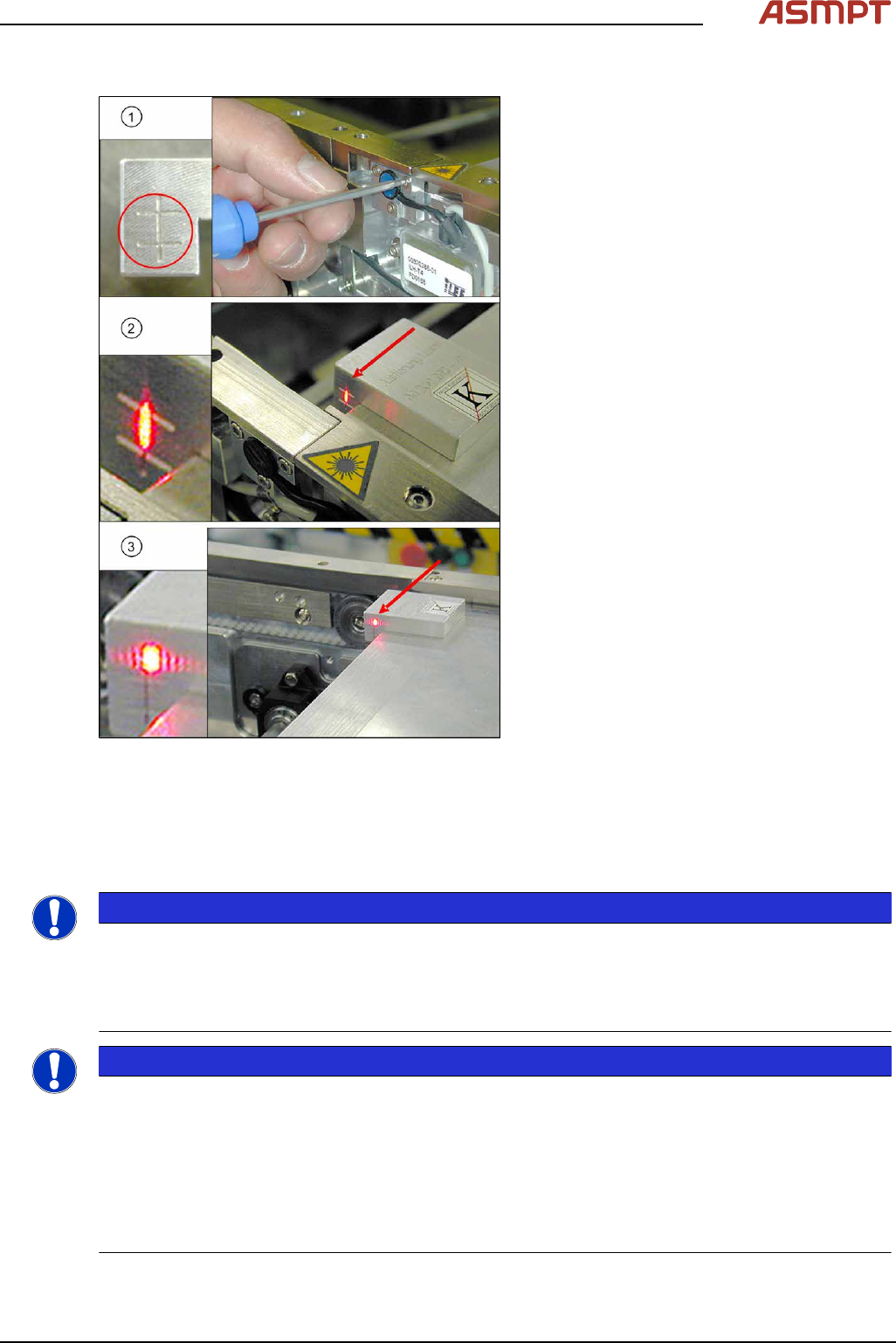
Fig.130: Focusing the laser beam (using example of X-
Series)
1. Setting the laser light barrier
2. Minimum width
3. Maximum width
► Set the maximum conveyor width.
► Select Enable safety mode in software.
► Activate the relevant laser diode using the
input/output functions in the station soft-
ware.
► Check the path of the laser beam with the
help of the gauge.
► With the help of the three setting screws,
adjust the laser beam to the center of the
gauge cross (1).
► Now position the conveyor to minimum
width(2) and check the setting.
► Check the PCB reference corner and
reteach, if necessary.
Repairing the fiber optic cables
To avoid machine downtimes, it is possible to repair fiber optic cables temporarily, using the repair
hose.
NOTICE
Repair hose for fiber optic cable LL3-TV05
► The repair hose may only be used for short periods to avoid machine downtimes.
► The repair hose may only be used once per fiber optic cable.
► The fiber optic cable must be replaced during the next repair or maintenance cycle.
NOTICE
No guarantee
► No guarantee is given if the fiber optic cable is repaired using the repair hose.
► There is no long-term experience with the repair hose.
► Depending on the board width, the intensity of the light beam may diminish in such a way that an
evaluation is no longer possible.
► The repair hose must not be bended. For this reason, there is an additional danger of rupture
after the repair, in areas where the fiber optic cable is routed in narrow radii.