Process Lens PL Service Manual_EN.pdf - 第78页
3 Replacing spare parts 78 Se rv ic e Ma nu al P ro ce ss L en s PL - 0 3/ 20 25 Fig.103: Removing clamping plate ► Insert the small pin or Allen key (3) to fix the actuator. ► Remove the two screws (2) fastening clam…

3 Replacing spare parts
Service Manual Process Lens PL - 03/2025 77
Overview
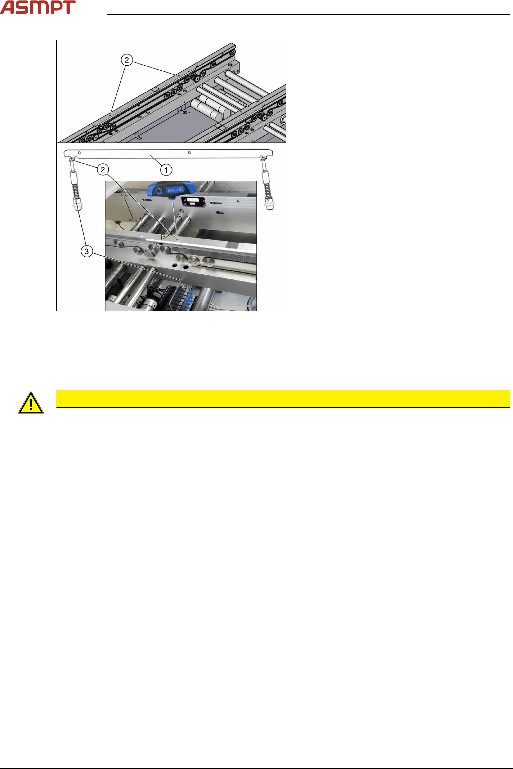
Fig.102: Clamping unit
1. Clamping unit on conveyor rail
2. Clamping unit complete
3. actuator
Removal
CAUTION
Small parts
► Take care not to lose any small parts.
► Take particular care not to let the screws fall into the conveyor rail when removing the screws or
clamping plate.
► Use the software or manually move the conveyor rail into a position which allows you best
access.
To move the conveyor side wall manually, pull the toothed belt of the width adjustment unit.
► Switch off the machine, disconnect it from the power supply and secure it to prevent unauthorized
reactivation.
► Remove the lifting table plate to make room for removing the actuator later (see chapter Repla-
cing the Lifting Table Plate [03114873-xx]).
3 Replacing spare parts
78 Service Manual Process Lens PL - 03/2025
Fig.103: Removing clamping plate
► Insert the small pin or Allen key(3) to fix
the actuator.
► Remove the two screws(2) fastening
clamping plate(1).
First loosen one screw slightly, and then
loosen the other screw slightly. After that,
remove both screws completely.
► Remove inserted Allen key and remove
the actuator from bottom side.
► Remove the clamping plate(1) with two
fastening screws carefully.
Installation
► Follow the removal instructions in reverse order for installation. Also observe the following
instructions:
CAUTION
Installation instructions
► Secure the two screws fastening the clamping unit with Loctite 241.
Calibrating the Track Zero Point
After completing all work to the width adjustment (adjustment unit, motor or belt of width adjustment),
you need to configure the adjustment unit before you configure the conveyor sides.
3 Replacing spare parts
Service Manual Process Lens PL - 03/2025 79
Procedure
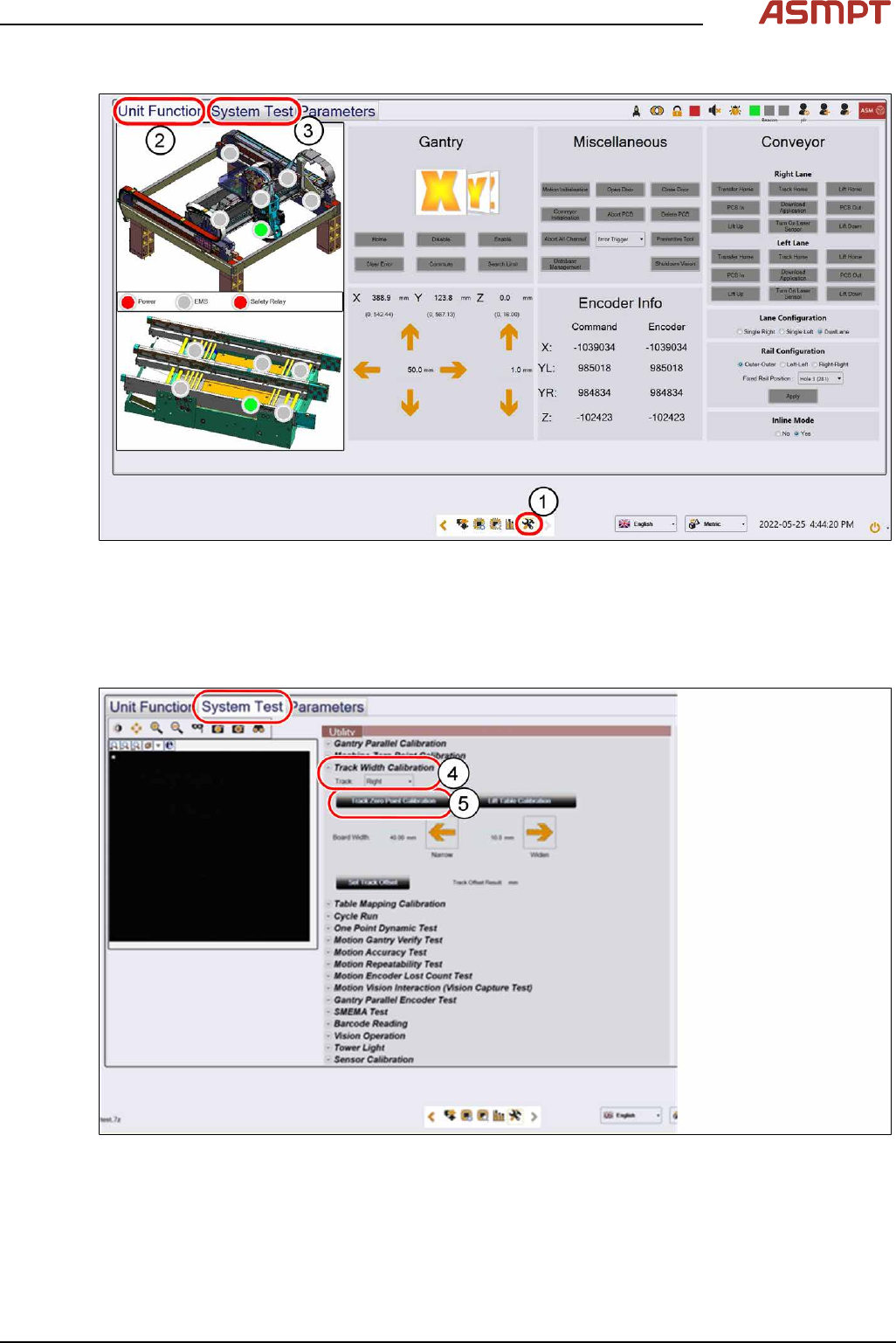
Fig.104: “Unit Function” tab and “System Test” tab
► Click on this icon(1) to enter the settings menu.
► Click on Unit Function(2) to enter the settings user menu.
► Switch to operator level Machine service.
► Click on System Test(3) to enter the calibration menu.
Fig.105: Settings in the “System Test” tab
► In the Track Width Calibration area(4) select the right track.
► Click on the Track Zero Point Calibration button(5) to calibrate the track zero point of the right
track.
► Repeat the calibration the same way for the left track.