Process Lens PL Service Manual_EN.pdf - 第150页
4 Machine - Calibrations 15 0 Se rv ic e Ma nu al P ro ce ss L en s PL - 0 3/ 20 25 Fig.226: Dual-Lane Mapping Plate position NOTICE Clean the mapping plate Clean the mapping plate using a piece of lint free cloth and a…
4 Machine - Calibrations
Service Manual Process Lens PL - 03/2025 149
Step 2
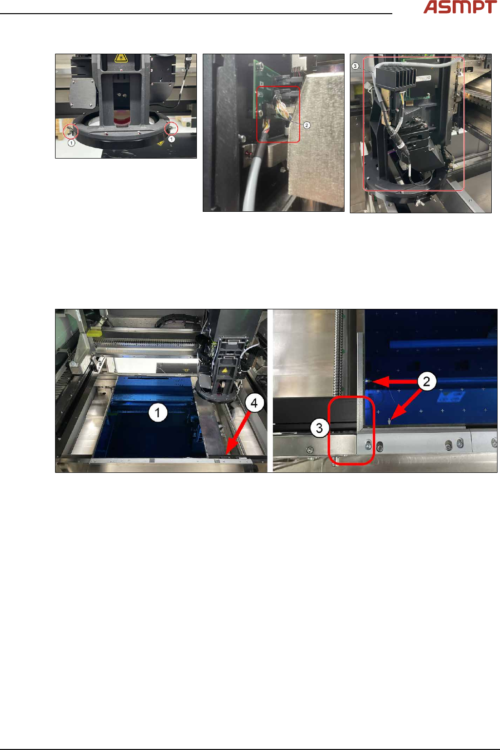
► Attach the coaxial lighting assembly from below the camera ring frame with the 2 wing nuts on
each side (1).
► Gently remove Low Ring connector (2) by holding onto the connector´s body (DO NOT pull
wire). Use a flat fead screwdrive to pry if necessary. Plug in coaxial lighting cable.
► (3) Ensure cable is laid as shown to avoid any interference during calibration.
Step 3
Fig.225: Single-Lane Mapping Plate position
► Put in the mapping plate (1).
(picture shows Single-Lane Mapping plate position)
► Refer to bottom left hand corner of the plate. The arrows on the long side is pointing towards the
left and the arrows on the short side of the plate is pointing towards the front. (2)
► Leading edge (3).
► Pull the sensor bar to the front and position under the leading aluminium edge of the plate. (4)
4 Machine - Calibrations
150 Service Manual Process Lens PL - 03/2025
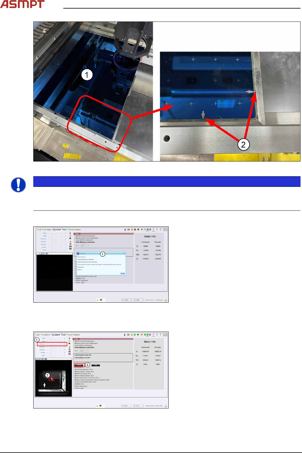
Fig.226: Dual-Lane Mapping Plate position
NOTICE
Clean the mapping plate
Clean the mapping plate using a piece of lint free cloth and alcohol. Dust and fingerprints can distort
images and cause the mapping to fail.
Step 4
Fig.227: Closing the cover
► Close the machine cover. (1)
► Click Ok.
ð The machine locks the cover, the table
raises to clamp the plate, and the cam-
era starts to move to the bottom right
corner of the plate.
Step 5
Fig.228: Setting the light
► Set 2D M-Ring_G light (1) about 10 and
all other lighting values to 0.
► The plate´s bottom right hand cross fidu-
cial comes into view. Click on the cross (2)
to centre the cross to the FOV.
4 Machine - Calibrations
Service Manual Process Lens PL - 03/2025 151
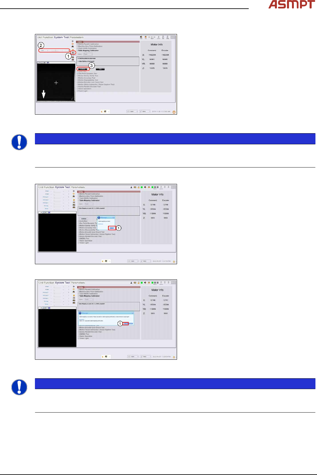
Step 6
Fig.229: “Focus” Icon
► Click on Focus icon (1).
► Set value (2) between 50 ~ 60.
► Click Continue (3) to start the teach table
mapping process.
The progress of the mapping is continu-
ously reported.
NOTICE
At 50% completion, the table towers, the stopper rises, and the plate will move forward to the stopper
to continue the second stage of the mapping. Do not be alarmed by this sudden movement. No user
intervention is required.
Step 7
Fig.230: Message
► A message pops up to report if the teach
process is completed.
Click Ok (1).
Fig.231: Message
► At the next message (2),
click OK to continue with verification (see
section Table Mapping: Verify)
or Cancel to end mapping teach.
NOTICE
If the mapping fails, clean the plate and repeat the procedure. Mapping failures are caused by a fail-
ure to read a fiducial on the plate – usually caused by fingerprint smudges on the fiducials. Verifica-
tion of the mapping results is necessary after a successful Teach.
► Lower the conveyor lift cable.
► Open the machine cover.
► Remove the mapping plate.
► Uninstall the coaxial light.