Process Lens PL Service Manual_EN.pdf - 第141页
4 Machine - Calibrations Se rv ic e Ma nu al P ro ce ss L en s PL - 0 3/ 20 25 14 1 Fig.201: Lighting During 2D/3D calibration, you can choose to perform auto-lighting or manually set the light- ing for each calibration…
4 Machine - Calibrations
140 Service Manual Process Lens PL - 03/2025
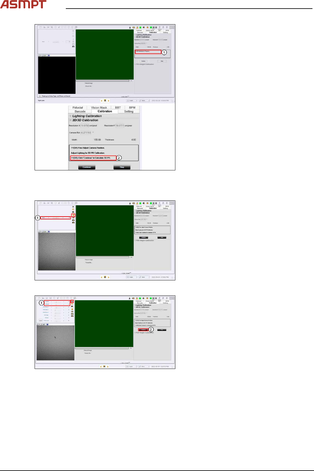
Fig.198: Messages
► Message shows 2D Calibration in Pro-
gress... (1).
► Message appears after point 5 com-
pleted(2).
Step 5
Fig.199: Focus
► Click on Focus icon(1).
► Adjust to value 50~60 (2).
Fig.200: Adjusting 3D Side
► Adjust 3D Side1 & 3D Side to value30(1).
► Click Continue (2) to start the 3D cali-
bration.
4 Machine - Calibrations
Service Manual Process Lens PL - 03/2025 141
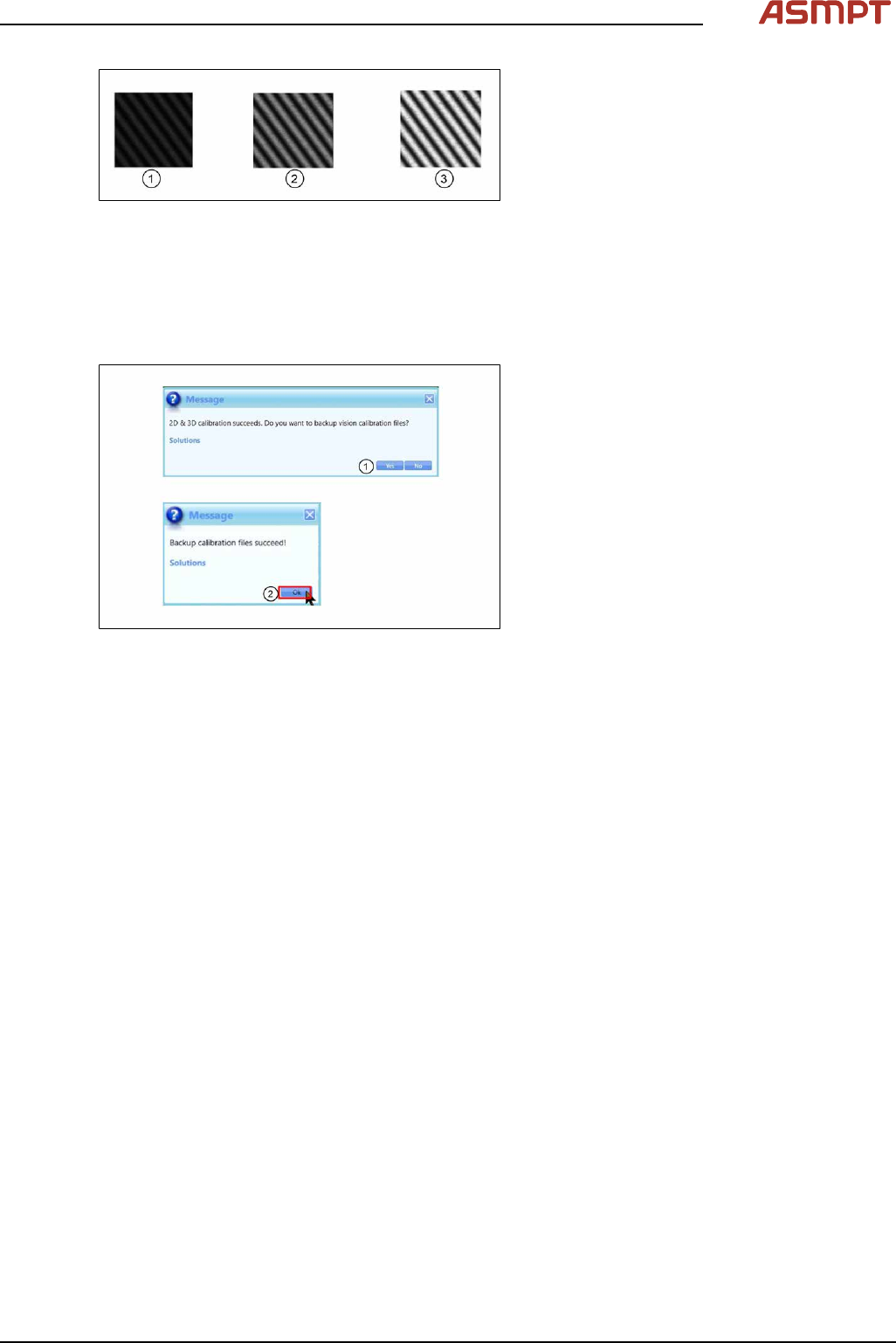
Fig.201: Lighting
During 2D/3D calibration, you can choose to
perform auto-lighting or manually set the light-
ing for each calibration. Note that for auto light-
ing there may be occasion where the auto light-
ing returns non optimized value, i.e., too bright
(3), or too dark (1). In this case, you may adjust
to achieve optimal lighting value (2) manually
based on experience.
To improve the lighting calibration result and
provide additional guidance to you, the software
performs image lighting check and prompt error
prior to 2D and 3D calibration.
Step 6
Fig.202: Messages
► Click Yes(1) to backup calibration files.
► Click Ok(2) to end.
► Unplug lighting cable and remove 2D/3D
calibration target.
If the 2D and 3D calibration fails:
► Clean the 2D glass target surface with a clean hair brush.
► Dust off the 3D glass target surface with a clean hair brush.
Dust and fingerprints cause light diffusion and hence calibration failure.
► Check if the DLP is working properly.
4 Machine - Calibrations
142 Service Manual Process Lens PL - 03/2025
4.2 Calibrations - Machine Zero Calibration
Purpose: Reference the relative position of the camera to a fixed position in the machine.
Step 1
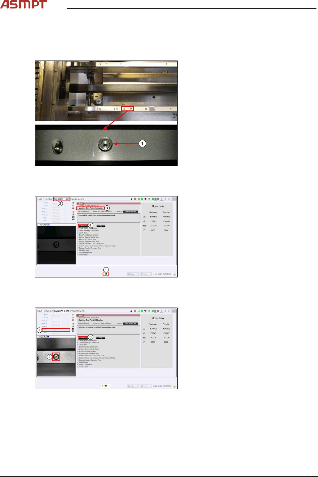
Fig.203: Reference
(1)Machine Zero Reference
► Locate the machine´s fixed fiducial on the
left side of the front conveyor. Check it is
clean and not obstructed from view.
► Close and lock the machine cover.
Step 2
Fig.204: “System test” tab
► Go to the DiagnosticPage. (1)
► Click System Test. (2)
► At Utility > Machine Zero Point Cali-
bration, click Start. (3)
ð The camera moves over to the
machine reference zero fiducial.
► Click Continue (4).
Step 3
Fig.205: Setting the brightness
► Set the 2D H_Ring (1) to brightness as
shown.
► Click on the centre of the fiducial (2).
► Click Continue (3) to proceed with cali-
bration. Live image window will turn dark
which is normal.
ð Message window will prompt user to
backup data.