Process Lens PL Service Manual_EN.pdf - 第99页
3 Replacing spare parts Se rv ic e Ma nu al P ro ce ss L en s PL - 0 3/ 20 25 99 Conveyor track Designation Description Track 1 1 (slave) Output area 2 (slave) Inspection area 3 (slave) Input area Track 2 4 (slave) Outpu…
3 Replacing spare parts
98 Service Manual Process Lens PL - 03/2025
Further installation is performed by following the above instructions in the reverse order. Also observe
the following instructions:
► Check the setting for the transmitter/receiver and correct if necessary.
► Calibrate the sensors of the PCB conveyor.
► Check the display on the fiber optic sensor. The value shown must be over 100. Check the value
for the various conveyor widths (red = output / green = input).
► Mark the optical system and the fiber optic cable at the fiber optic sensor with the glue dot sup-
plied. The glue dot indicates that the fiber optic cable has already been repaired and that a re-
placement is compulsory at the next defect.
Replacing the fiber optic sensor
Parts
Fig.133: Fiber optic sensor
03093294-xx Fiber optic sensor WLL180T-M pre-programmed SXa (master)
03093295-xx Fiber optic sensor WLL180T-F pre-programmed SXa (slave)
Equipment and tools
00353832-xx Allen key set
Side cutter
Cable ties
Overview
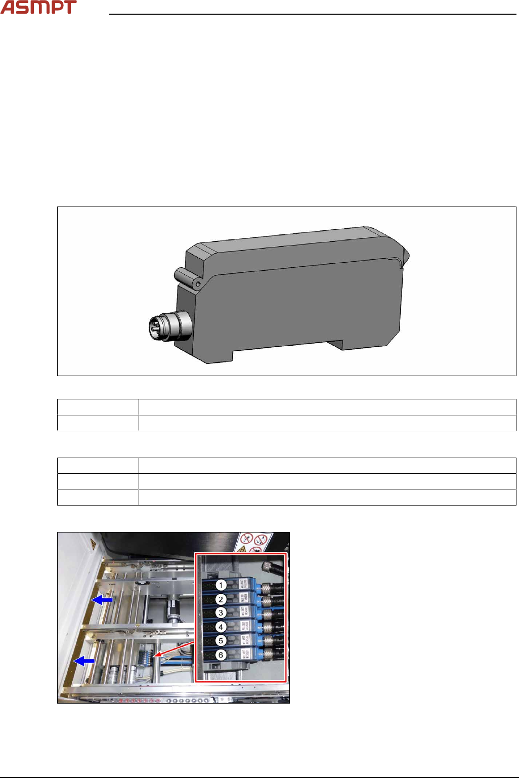
Fig.134: Fiber optic sensors
The fiber optic sensors are located at location 2
under the lifting table plate.
(1) to (6): fiber optic sensors for the input area,
placement area and output area.
The receivers are always at the top of the fiber
optic sensors and the transmitters at the bot-
tom.
3 Replacing spare parts
Service Manual Process Lens PL - 03/2025 99
Conveyor track Designation Description
Track 1 1 (slave) Output area
2 (slave) Inspection area
3 (slave) Input area
Track 2 4 (slave) Output area
5 (slave) Inspection area
6 (master) Input area
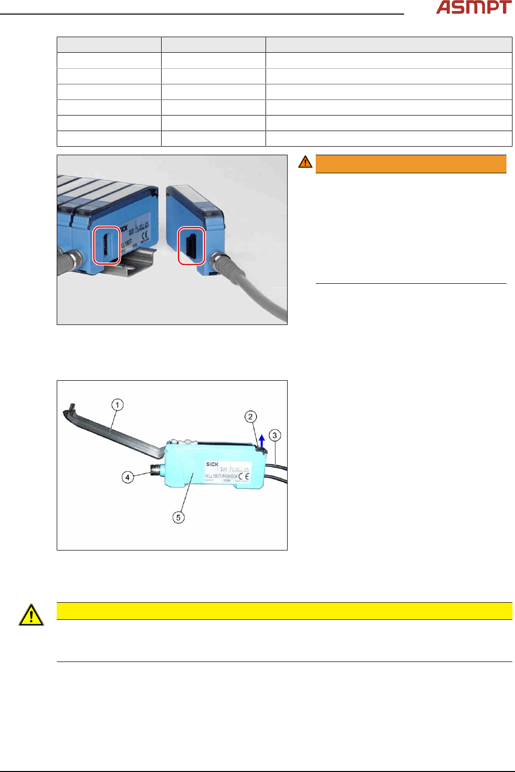
Fig.135: Plug-and-socket connections
WARNING!
The adjacent fiber optic sensors are
connected via plug-and-socket con-
nections on the side.
Before dismantling the fiber optic sensors
always separate them a bit.
Do not lift the fiber optic sensors off
without separating them first. If you do so,
you may damage the plug-and-socket
connection.
.
Each sensor has two fiber optic cables connected (transmitter/receiver), which belong to the same
conveyor belt (segment).
Fig.136: Fiber optic sensor
1. Cover
2. Locking the fiber optic cables
top = open
bottom = closed
3. Fiber optic cable
Top: input (from receiver)
Bottom: output (to transmitter)
4. Electrical connection
5. Electrical connection to neighboring fiber
optic sensor (under the plastic cover)
Removal
CAUTION
Do not bend fiber optic cables
► Make sure you do not bend the fiber optic cables. Otherwise the cable will become cloudy and
no longer transmit the signal properly.
► Use the software or manually move the conveyor rail into a position which allows you best
access.
To move the conveyor side wall manually, pull the toothed belt of the width adjustment unit.
► Switch off the machine, disconnect it from the power supply and secure it to prevent unauthorized
reactivation.
3 Replacing spare parts
100 Service Manual Process Lens PL - 03/2025
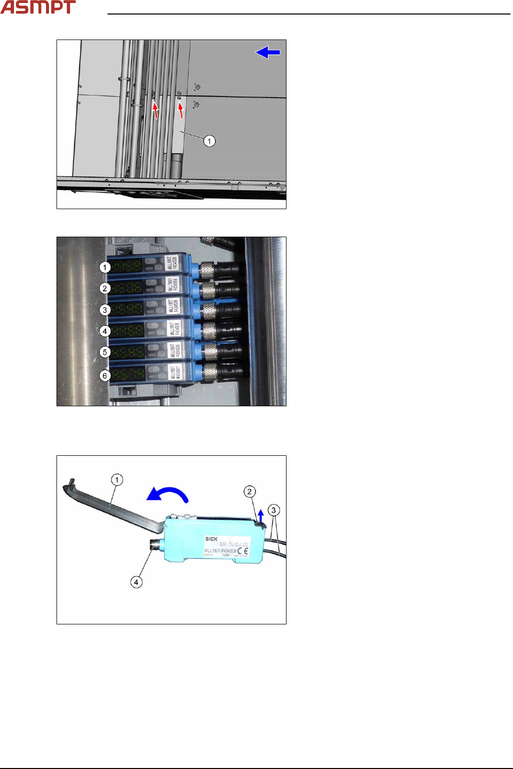
Fig.137: Cover
► Remove the two screws fastening the
cover(1) and remove the cover.
Fig.138: Fiber optic sensors
The individual fiber optic sensors are connected
to one another via a small terminal strip.
Dismantle the fiber optic sensors one after one
beginning with (6) (track2) until you have
reached the fiber optic sensor to be replaced.
Perform the following tasks at each fiber optic
sensor:
Dismantling a fibre optic sensor
Fig.139: Fiber optic sensor
► Open the cover(1) on the fiber optic
sensor.
► Open the lock(2) on the fiber optic
cables(3) and then pull off the fiber optic
cables. You might like to mark their posi-
tions to make clear assignment easier
later on.
► Disconnect from the power supply(4). You
may want to mark the position, to make
clear assignment easier later on.
► Pull the fiber optic sensor slightly away from the other fiber optic sensors, to loosen the electrical
connection to the neighboring fiber optic sensor.
Now you can pull the sensor up and off the strip.
► Repeat these steps if needed for any other fiber optic sensors.