Process Lens PL Service Manual_EN.pdf - 第148页
4 Machine - Calibrations 14 8 Se rv ic e Ma nu al P ro ce ss L en s PL - 0 3/ 20 25 Fig.221: message ► A message asking for the mapping data file pops up. (1) ► Click Ok . (2) Fig.222: Choosing file ► Choose mp_mess.da…
4 Machine - Calibrations
Service Manual Process Lens PL - 03/2025 147
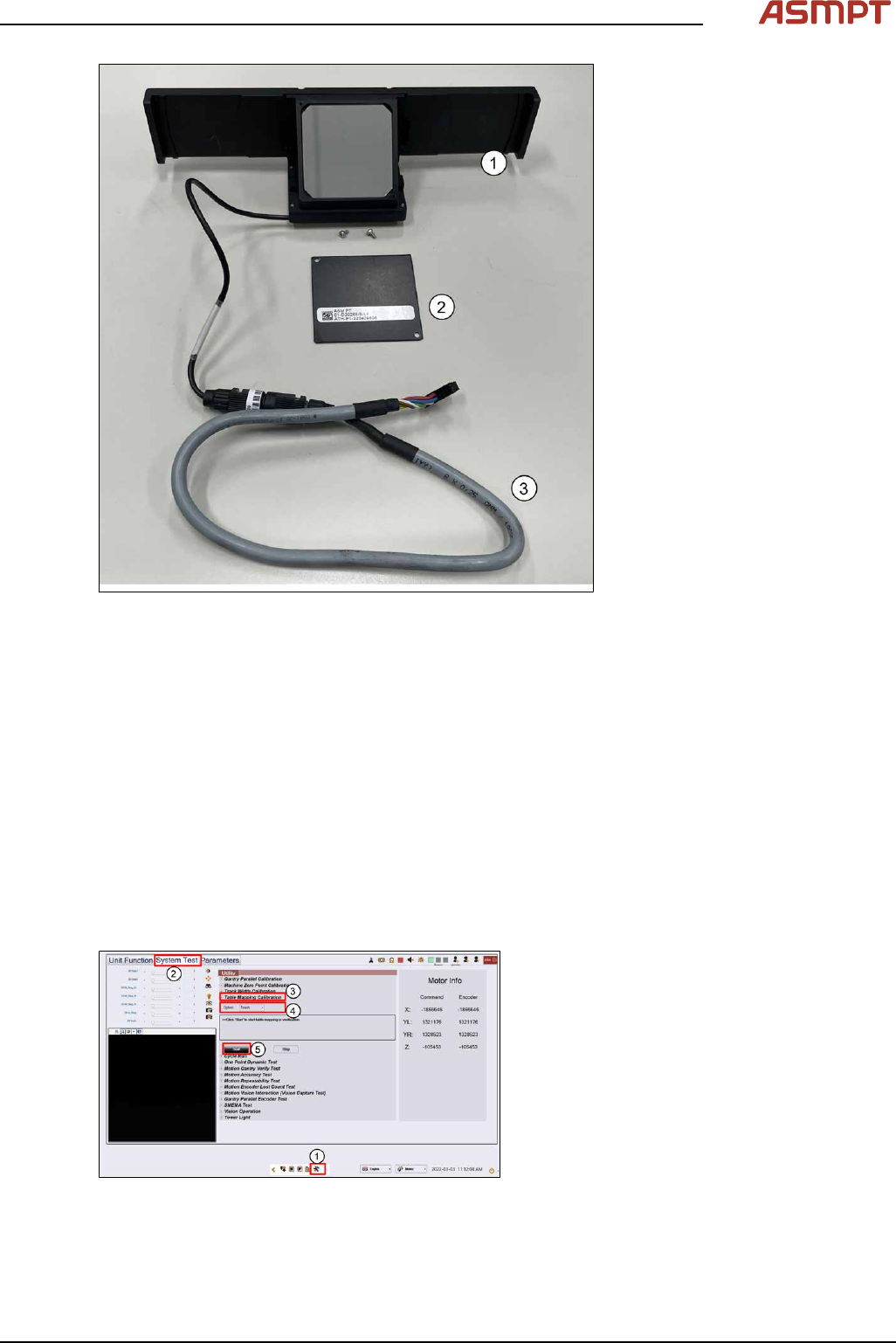
Fig.219: Process Lens PL HD [03251137-xx]
► Prepare the coaxial light assembly. The Coaxial light consists of a lighting assembly(1) and a
cable(3). The glass surfaces are protected by a cover(2) secure by 2 screws.
► Remove screws and the protective covers (2).
► Clean the glass surfaces of the lighting assembly if necessary with a lint free cloth.
► The Process Lens PL uses the SIPLACE SX-Series mapping plate version 5 (1). Each Mapping
glass plate has its own unique positional data map saved in a CD or in a Flash drive. The data is
in stored in a file named mp_mess.dat.
► Open the mp_mess.dat file in the mapping CD or flash drive that comes with the mapping plate.
Compare the plate reference number (2) against the number labeled on the plate. They should
be the same.
4.4.1 Table Mapping: Teach
Step 1
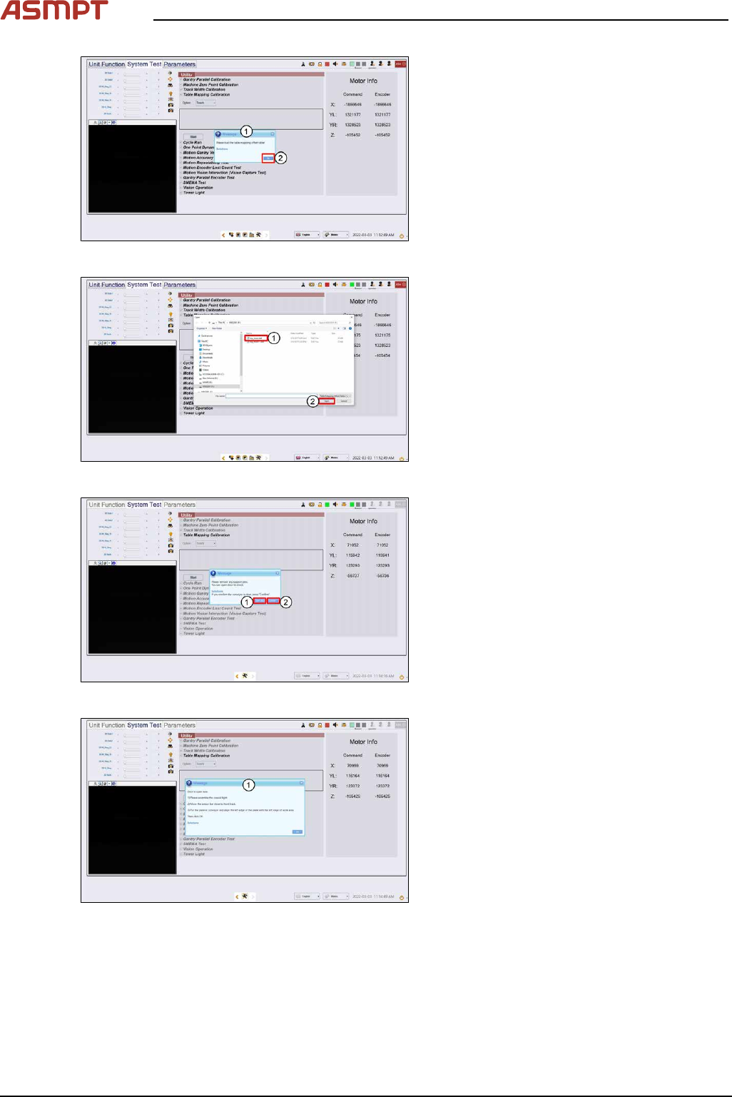
Fig.220: “System test” tab
► Go to the DiagnosticPage (1).
► Click System Test (2).
► Go to Utility, Table Mapping Calibration
(3).
► Under Option, select Teach (4).
► Click Start (5).
4 Machine - Calibrations
148 Service Manual Process Lens PL - 03/2025
Fig.221: message
► A message asking for the mapping data
file pops up. (1)
► Click Ok. (2)
Fig.222: Choosing file
► Choose mp_mess.dat file (1).
► Click Open (2), data loading.
Fig.223: Opening the door
► A message asking to remove any support
pins. Click Open door (1).
► Click Confirm (2).
► Wait while the conveyor adjust to a width
of 560mm.
Fig.224: Opening the door
► Open door, assemble coaxial light as
shown in next step.
4 Machine - Calibrations
Service Manual Process Lens PL - 03/2025 149
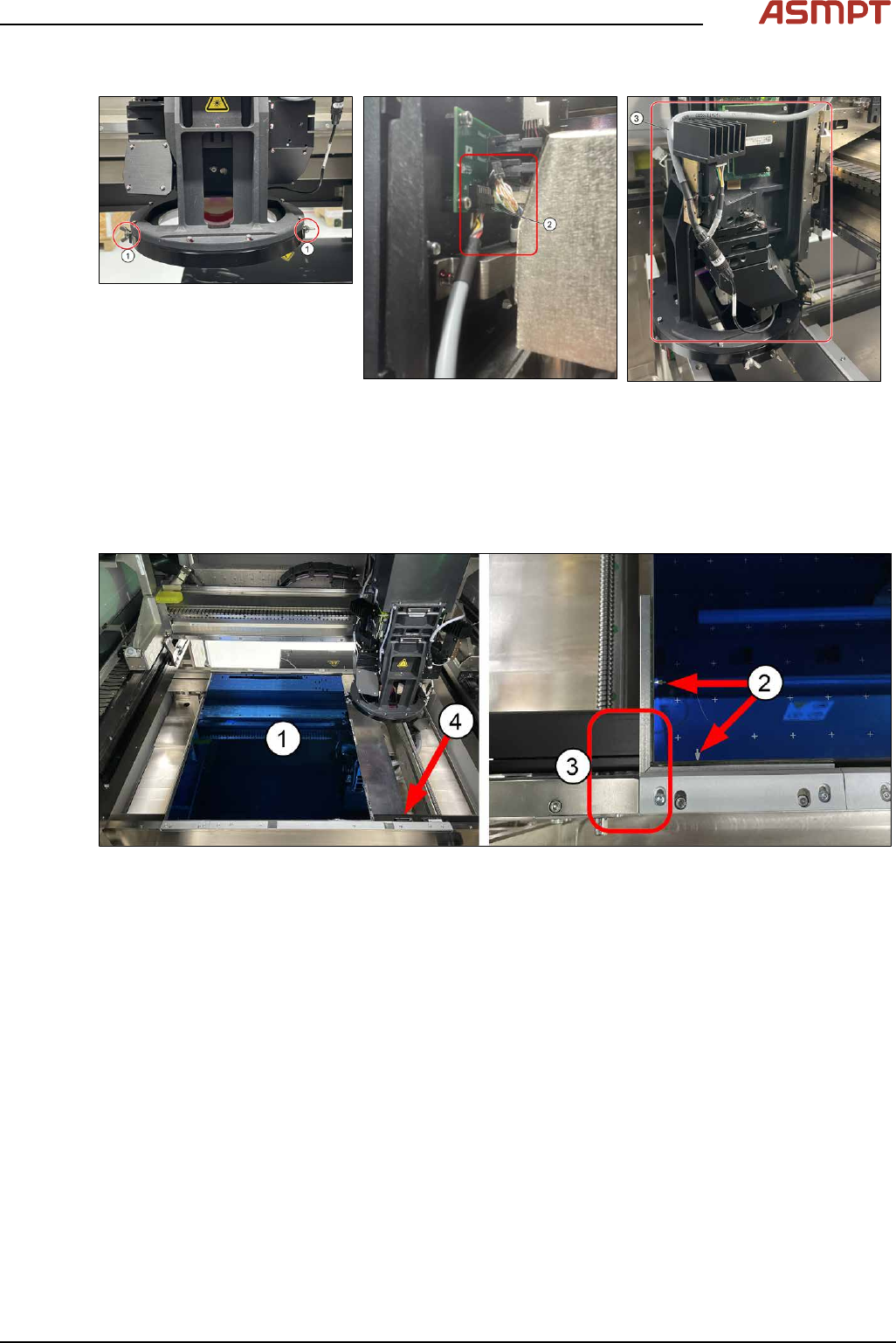
Step 2
► Attach the coaxial lighting assembly from below the camera ring frame with the 2 wing nuts on
each side (1).
► Gently remove Low Ring connector (2) by holding onto the connector´s body (DO NOT pull
wire). Use a flat fead screwdrive to pry if necessary. Plug in coaxial lighting cable.
► (3) Ensure cable is laid as shown to avoid any interference during calibration.
Step 3
Fig.225: Single-Lane Mapping Plate position
► Put in the mapping plate (1).
(picture shows Single-Lane Mapping plate position)
► Refer to bottom left hand corner of the plate. The arrows on the long side is pointing towards the
left and the arrows on the short side of the plate is pointing towards the front. (2)
► Leading edge (3).
► Pull the sensor bar to the front and position under the leading aluminium edge of the plate. (4)