Process Lens PL Service Manual_EN.pdf - 第45页
3 Replacing spare parts Se rv ic e Ma nu al P ro ce ss L en s PL - 0 3/ 20 25 45 Installation Follow the removal instructions in reverse order for installation. Also observe the following instructions. CAUTION Do not ove…
3 Replacing spare parts
44 Service Manual Process Lens PL - 03/2025
3.2.1.3 Replacing the high ring light board
Parts
03254621-xx High Ringlight HD
Equipment and tools
●
Allen key size 1.5
●
Allen key size 2.5 (T shaped)
●
Philips screwdriver
Requirements
●
Machine is switched off.
●
It is advisable to dismantle the low ring light assembly as well for better access.
●
Use a T shaped Allen key to carry out this task.
Removal
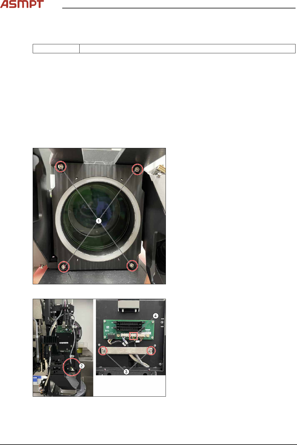
Fig.47: Removing the four screws
► Remove the four screws(1).
Fig.48: Unplugging the cable
► Remove the able connector as shown(2).
► Loosen the two screws(3), remove the
cable clamp.
► Unplug the cable(4).
3 Replacing spare parts
Service Manual Process Lens PL - 03/2025 45
Installation
Follow the removal instructions in reverse order for installation. Also observe the following instructions.
CAUTION
Do not overtighten the screws
When the high ring light board is reassembled, one must not overtighten the screws, as this may
damage the high ring light board.
3.2.1.4 Checking the function of the low ring light and the high ring light
Requirements
●
Machine is switched on.
●
Machine doors are open.
●
The low ring light and the high ring light are mounted.
Checking the function
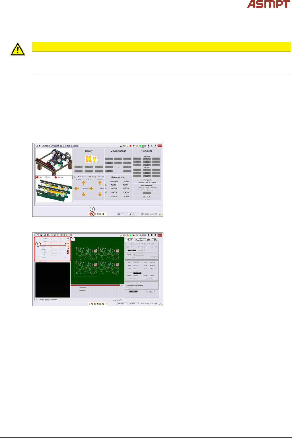
Fig.49: Control button
► Go to the diagnostic pages and press the
control button(1).
Fig.50: Lighting control page
► On the Lighting control page click on the
lighting control button.
► The Lighting box(1) is displayed.
► In the 2D Lighting Setup section push the
slider to the right.
► Starting with slider bar M-Ring_G(2)
check the green light of the low ring light.
► Check if all LEDs are functional and flash-
ing by using a mirror or view from under-
neath the optical head.
► Approach the same for all other slider bars
in that section.
3 Replacing spare parts
46 Service Manual Process Lens PL - 03/2025
3.2.2 DLP
3.2.2.1 Replacing the DLP left and right controller
Parts
03264112-xx DLP controller HD (L)
03264113-xx DLP controller HD (R)
Equipment and tools
●
Allen key size 1.5
●
Allen key size 2.0
●
Philips screwdriver
Requirements
●
Machine is switched off.
Removal
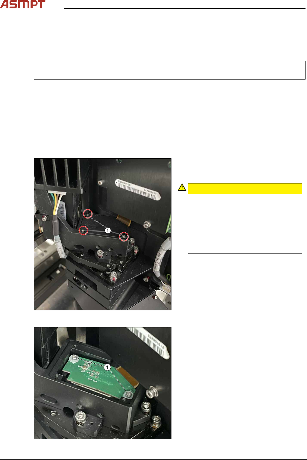
Fig.51: Removing the small screws
► Remove the screws (1) using a Philips
screwdriver to remove the cover of the
DMD module (connector).
CAUTION!
Small screws
The screws are very small. When the
screws fall into the machine they may
damage it.
Make sure the screws don’t fall into the
machine.
Make sure no screw is left behind inside
the machine.
.
Fig.52: Removing the screws
► Remove the screws and washers (1) by
using an Allen key size 1.5.
► Carefully lift the connector of the DMD
module.