Process Lens PL Service Manual_EN.pdf - 第125页
3 Replacing spare parts Se rv ic e Ma nu al P ro ce ss L en s PL - 0 3/ 20 25 12 5 Fig.177: “System Test” tab ► Open the Diagnostic page. ► Go to the tab System Test (1) . ► Click on the button Track zero point cali- b…
3 Replacing spare parts
124 Service Manual Process Lens PL - 03/2025
3.5.2.4 Changing the motor for the width adjustment
Parts
03106082-xx BLM-4280-24 motor
Equipment and tools
●
Allen key size 3.0
Requirements
●
Machine is switched off.
●
Lifting table plate is dismantled.
Removal
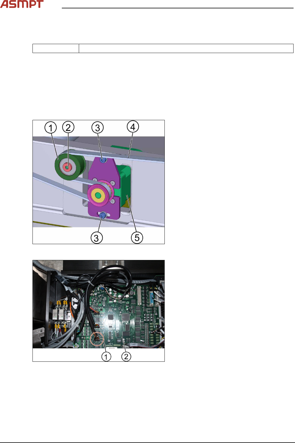
Fig.175: Motor for the width adjustment
1. Tension ring
2. Screw A
3. Screw B (2 x)
4. Belt
5. Motor
Unscrew the screw A(2) to loosen the tension
(1).
► Unscrew the 2 screws B(3) using an Allen
key size 3.0
Fig.176: TSP400
► Disconnect the connectors(1) of the
TSP400(2).
► Replace the motor.
► Connect the connectors(1) to the
TSP400(2).
► Tighten the screws.
► Go to section 3.16.1 Check system test to
check the function.
Installation
Follow the removal instructions in reverse order for installation.
Check system test
Requirements
●
Machine is switched off.
3 Replacing spare parts
Service Manual Process Lens PL - 03/2025 125
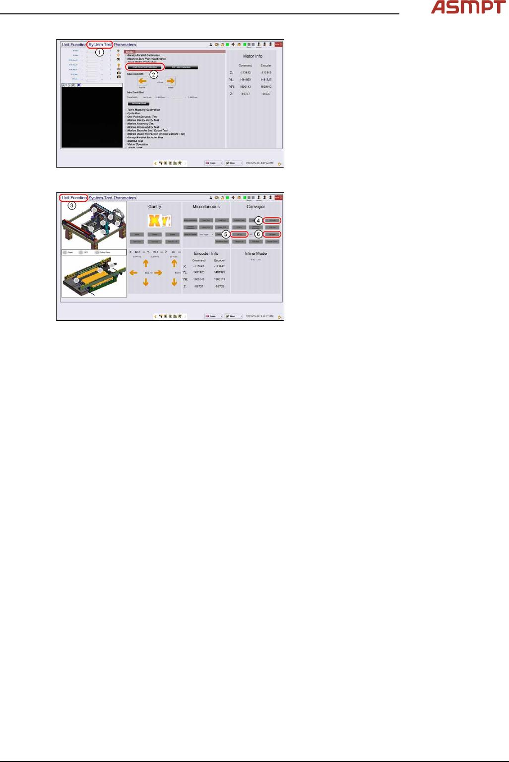
Fig.177: “System Test” tab
► Open the Diagnostic page.
► Go to the tab System Test(1).
► Click on the button Track zero point cali-
bration(2).
► A message will indicate that the calibration
was successful.
Fig.178: “Unit function” tab
► Go to the tab Unit function(3).
► Proceed to the conveyor section and press
the buttons Lift Home(4), Lift up(5) and
Lift down(6) to check the function of the
lifting table.
► On screen messages will confirm the suc-
cessful function test of the lifting table.
► If the conveyor system does not move or
any fault message occurs, the conveyor
system needs to be adjusted.
3 Replacing spare parts
126 Service Manual Process Lens PL - 03/2025
3.5.2.5 Changing the motor of the lifting table
Parts
03064983-xx BLDS motor with PLG and brake
Equipment and tools
●
Allen key size 5.0
Requirements
●
Machine is switched off.
Remove the motor of the lifting table
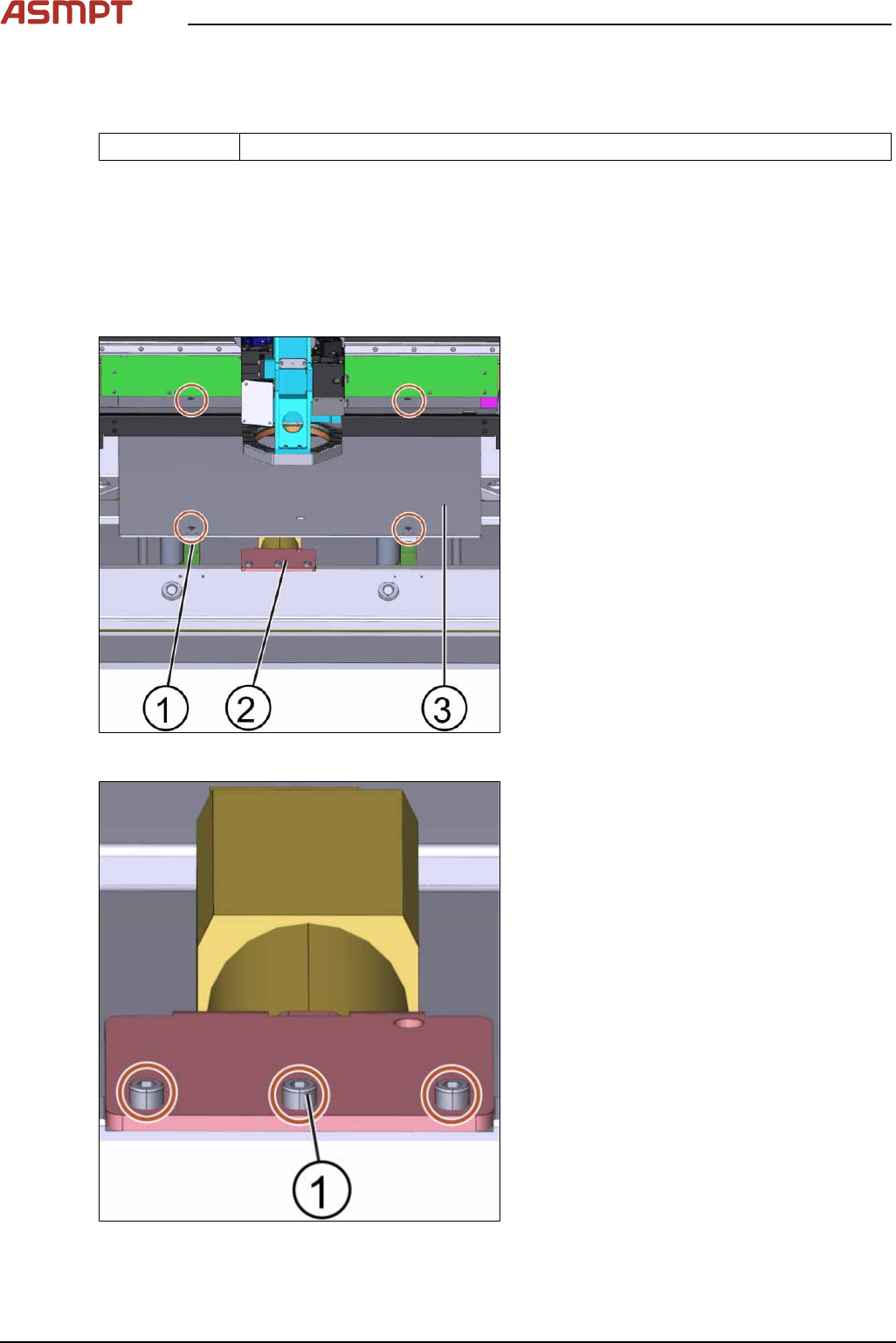
Fig.179: Lifting plate
1. Screw (4 x)
2. Motor of the lifting table plate
3. Lifting table plate
► Unscrew the screws(1) off the lifting table
plate(3) using an Allen key size 5.0.
► Remove the lifting table plate(3).
► Disconnect all connectors from the
TSP400.
Fig.180: Lifting table motor
► Unscrew the 3 screws(1) off the lifting
table motor using an Allen key size 5.0.