Process Lens PL Service Manual_EN.pdf - 第56页
3 Replacing spare parts 56 Se rv ic e Ma nu al P ro ce ss L en s PL - 0 3/ 20 25 3.5 Replacing spare parts at the conveyor DANGER Observe User Manual ► Please observe the safety instructions in the user manual for all wo…
3 Replacing spare parts
Service Manual Process Lens PL - 03/2025 55
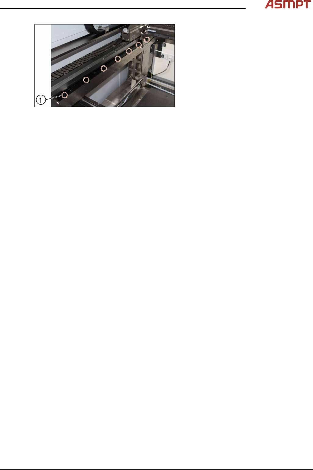
Fig.68: Tightening the screws
► Tighten the seven screws(1).
► Check the space between the reader and
the scale bar by using the 2.1 mm spacer
provided.
► Check the lights of the encoder at the back
of the machine.
► Slowly move the gantry backwards and
forwards. See section 3.3.2 "Color code for
the encoder readers" [}51].
► Adjust the brackets when the lights indic-
ate to do so.
► The steps to change the other scale bar are identical.
► Check the alignment of the y scale bar. Go to section 3.3.3 "Checking the alignment of the en-
coder reader of the Y gantry" [}52] and section 3.3.3 "Checking the alignment of the encoder
reader of the Y gantry" [}52].
► Tighten the seven screws(1).
► Check the space between the reader and the scale bar by using the 2.1 mm spacer provided.
► Check the lights of the encoder at the back of the machine.
► Slowly move the gantry backwards and forwards. See section 3.3.2 "Color code for the encoder
readers" [}51].
► Adjust the brackets when the lights indicate to do so.
► The steps to change the other scale bar are identical.
► Check the alignment of the y scale bar. Go to section 3.3.3 "Checking the alignment of the en-
coder reader of the Y gantry" [}52] and section 3.3.3 "Checking the alignment of the encoder
reader of the Y gantry" [}52].
3 Replacing spare parts
56 Service Manual Process Lens PL - 03/2025
3.5 Replacing spare parts at the conveyor
DANGER
Observe User Manual
► Please observe the safety instructions in the user manual for all work!
CAUTION
Do not loosen or remove the wrong screws
The following applies to all work performed on the conveyor:
► Make sure that you do not loosen or remove any other screws except those ones explicitly men-
tioned. Loosening other screws could lead to irreparable misalignment or damage to the con-
veyor.
CAUTION
Moving the conveyor rails
► The fixed conveyor rail is fastened by screws, the moveable conveyor rail can be moved by
carefully pulling on the toothed belt of the width adjustment.
► After moving the conveyor rail manually, you may need to teach the conveyor rail position during
the conveyor reference run and recalibrate the light barriers.
3.5.1 Dual-lane conveyor
3.5.1.1 Conveyor - overview
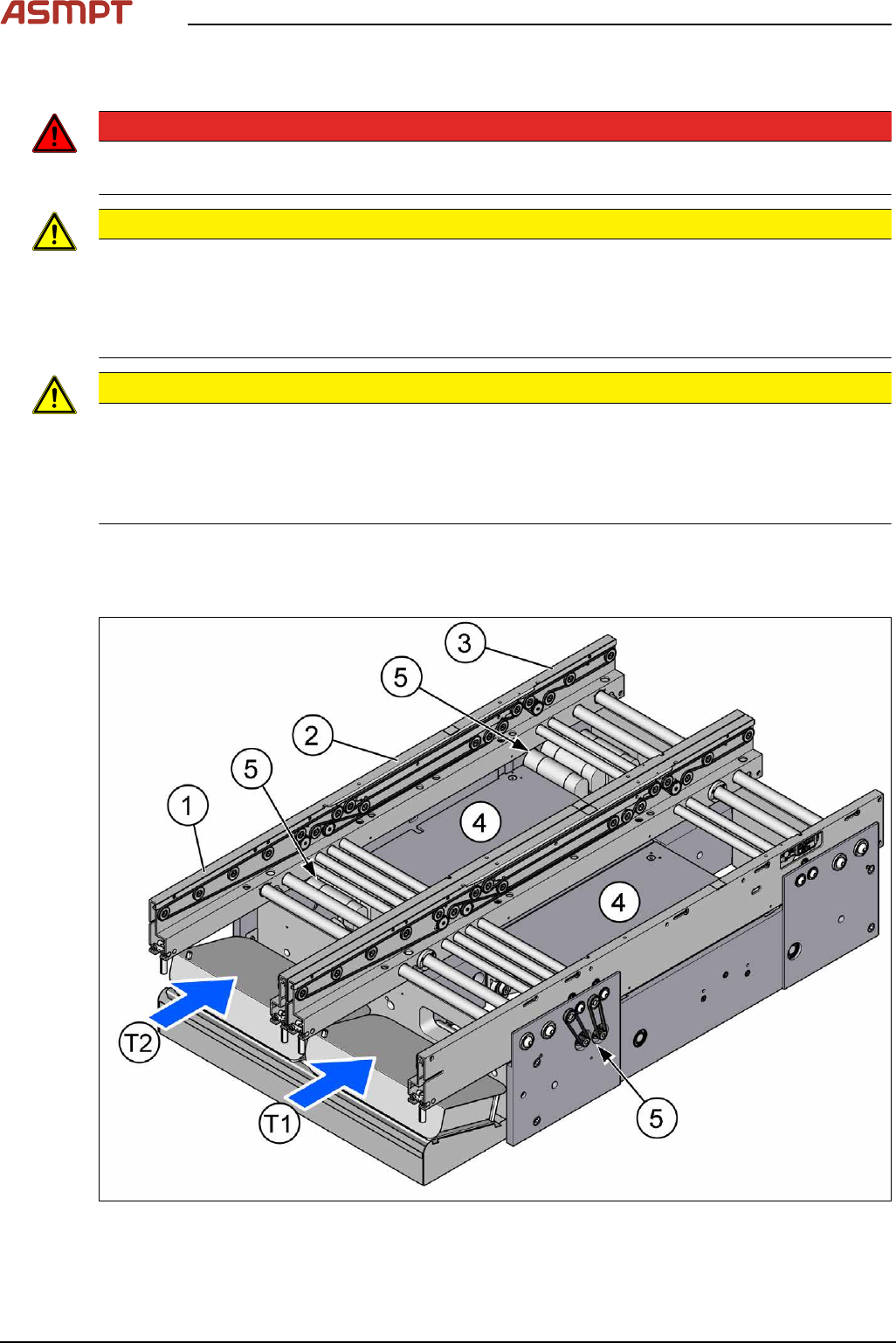
Fig.69: Conveyor overview - part 1
3 Replacing spare parts
Service Manual Process Lens PL - 03/2025 57
T1 Conveyor Track 1
T2 Conveyor Track 2
1 Input area
2 Inspection area
3 Output area
4 Lifting tables
Lifting table
5 Conveyor drives
Conveyor drive
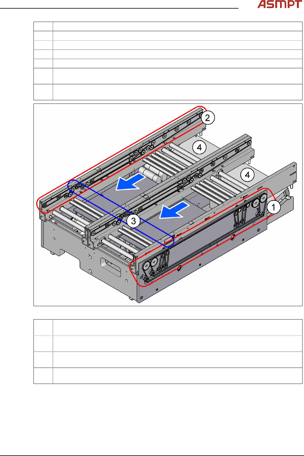
Fig.70: Conveyor overview - part 2
1 Width adjustment
Width Adjustment
2 Conveyor belts
Conveyor belt, belt drive and hexagonal shaft
3 Light barriers
Fiber Optic Cable and Light Barriers
4 Conveyor control TSP420
Boards
The flexible dual conveyor has two conveyor tracks that are electrically and mechanically independent
of one another.
By default, the fixed conveyor rails are in the "outer" position.
Optionally, the fixed conveyor rail can be selected - right/right or left/left.
Setting the fixed conveyor rail
The PCB dual conveyor can also be operated as a flexible single conveyor, no license is required for
Process Lens.