Process Lens PL Service Manual_EN.pdf - 第29页
3 Replacing spare parts Se rv ic e Ma nu al P ro ce ss L en s PL - 0 3/ 20 25 29 Fig.20: Removing the screws ► Remove the two screws (1) that connect the connector with the DMD module by using an Allen key size 1.5. ► …
3 Replacing spare parts
28 Service Manual Process Lens PL - 03/2025
3.1.2 DLP
3.1.2.1 Replacing the DLP left and right controller
Parts
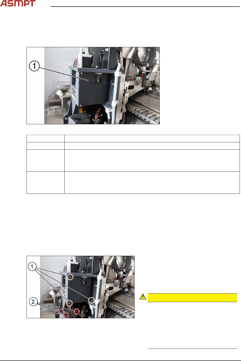
Fig.18: Right DLP module (1)
03139342-xx In-house left DLP module
03139345-xx In-house right DLP module
03250887-xx DLP Controller Left G2
●
Single Lane: PL-0144 and above
●
Dual Lane: PD0030 and above
03250888-xx DLP Controller Right G2
●
Single Lane: PL-0144 and above
●
Dual Lane: PD0030 and above
Equipment and tools
●
Allen key size 1.5
●
Allen key size 2.0
●
Philips screwdriver
Requirements
●
Machine is switched off.
Removal
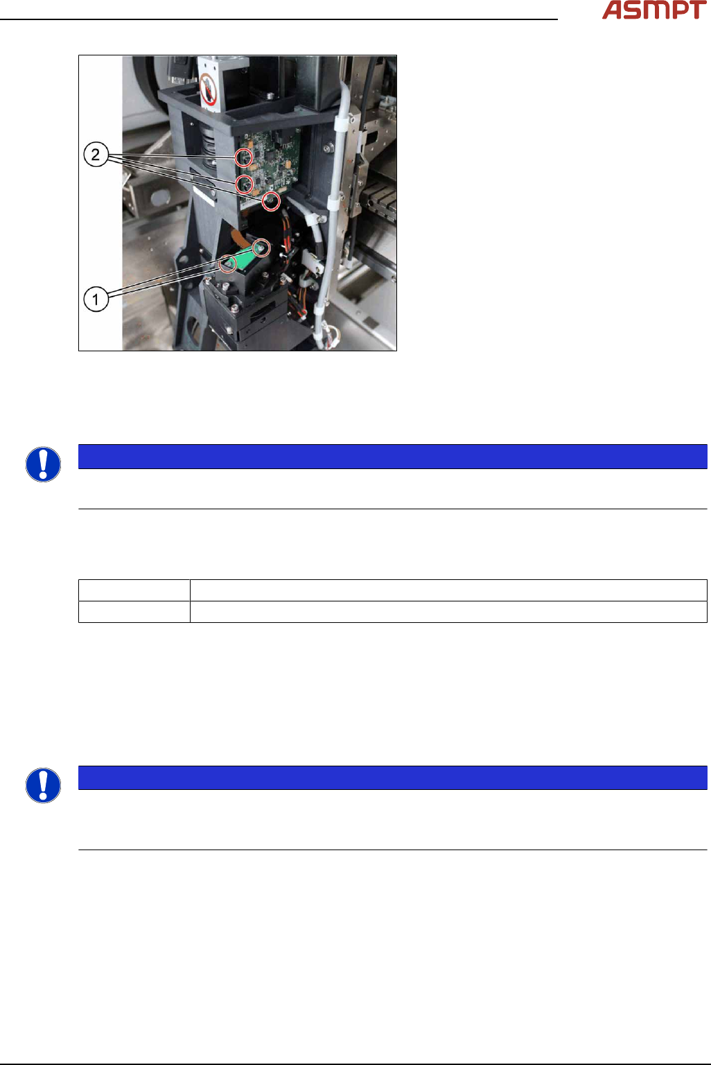
Fig.19: Removing the screws
► Remove the three screws(1) using a
Philips screwdriver to remove the cover of
the DLP module (circuit board).
► Remove the three screws(2) using a
Philips screwdriver to remove the cover of
the DMD module (connector).
CAUTION!
Small screws
The screws are very small. When the
screws fall into the machine they may
damage it.
Make sure the screws don’t fall into the
machine.
Make sure no screw is left behind inside
the machine.
.
3 Replacing spare parts
Service Manual Process Lens PL - 03/2025 29
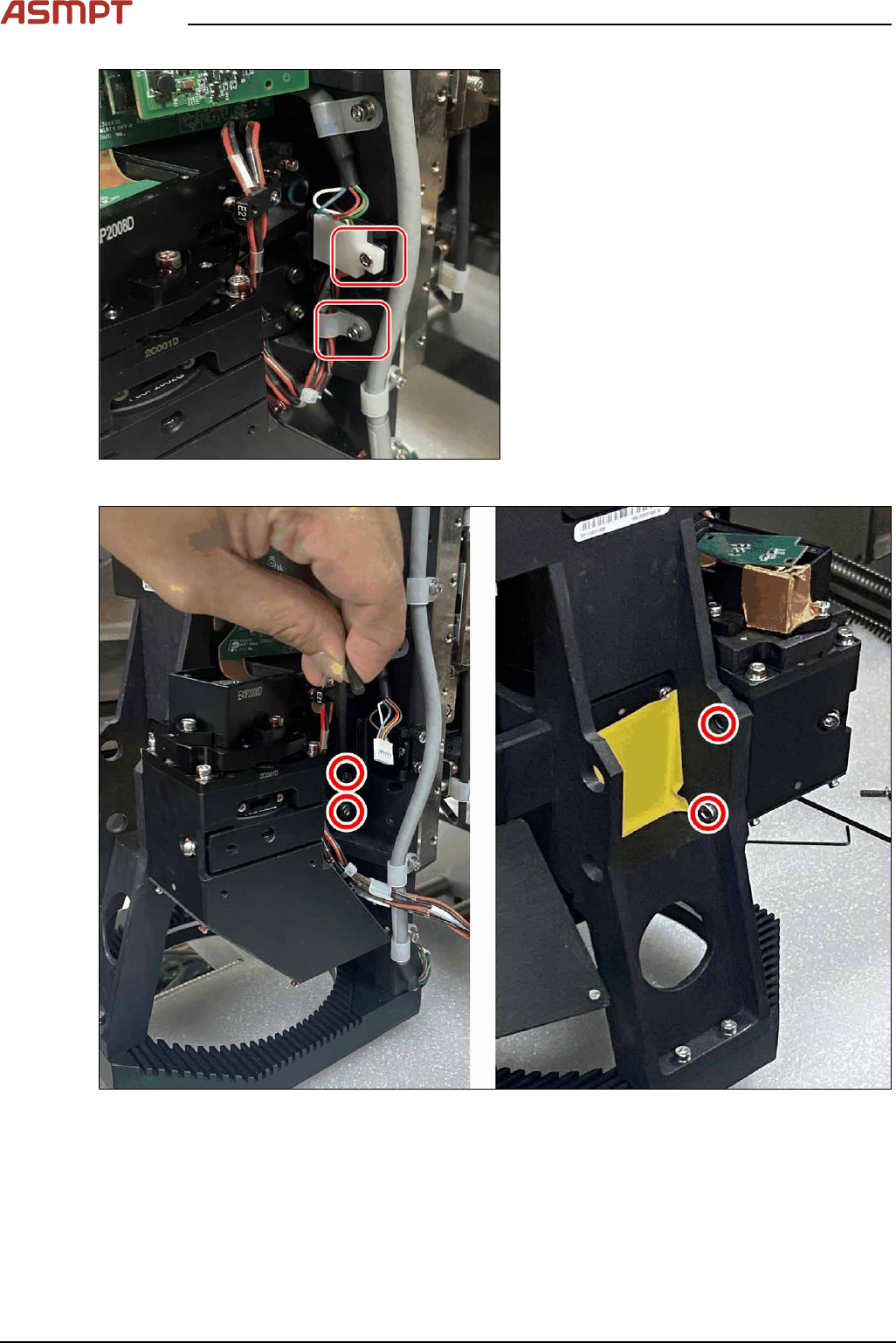
Fig.20: Removing the screws
► Remove the two screws(1) that connect
the connector with the DMD module by
using an Allen key size 1.5.
► Carefully lift the connector of DMD mod-
ule.
► Remove the three screws(2) of the DLP
module by using an Allen key size 2.0.
► Remove the circuit board and replace it.
► The steps for the left and the right module
are identical.
Installation
Follow the removal instructions in reverse order for installation.
NOTICE
Modules are not interchangeable
Be aware that the two modules are not interchangeable.
3.1.2.2 Replacing the projector
Parts
03295671‑xx Left Projector G2
03295672-xx Right Projector G2
Equipment and tools
Projector adjustment jig [03296502‑xx]
Requirements
●
Machine is switched off.
Removal
NOTICE
Left and right projector
You need to remove the left and the right projector.
The first step „Removal of the optical head” needs to be done only for the left projector.
► Remove the optical head (only relevant for the left protector). See also 3.1.1 "Optical head"
[}21].
► Remove the DLP Controller. See also 3.1.2.1 "Replacing the DLP left and right controller" [}28].
3 Replacing spare parts
30 Service Manual Process Lens PL - 03/2025
Fig.21: Removing the screws
► Remove the two screws that hold the
cable and the cable holder.
Fig.22: Removing the screws
► Remove the four screws that secure the module.
► Remove the module.