Process Lens PL Service Manual_EN.pdf - 第26页
3 Replacing spare parts 26 Se rv ic e Ma nu al P ro ce ss L en s PL - 0 3/ 20 25 3.1.1.3 Replacing the high ring light board Parts 03122924-xx High ring light board Equipment and tools ● Allen key size 1.5 ● Allen key si…
3 Replacing spare parts
Service Manual Process Lens PL - 03/2025 25
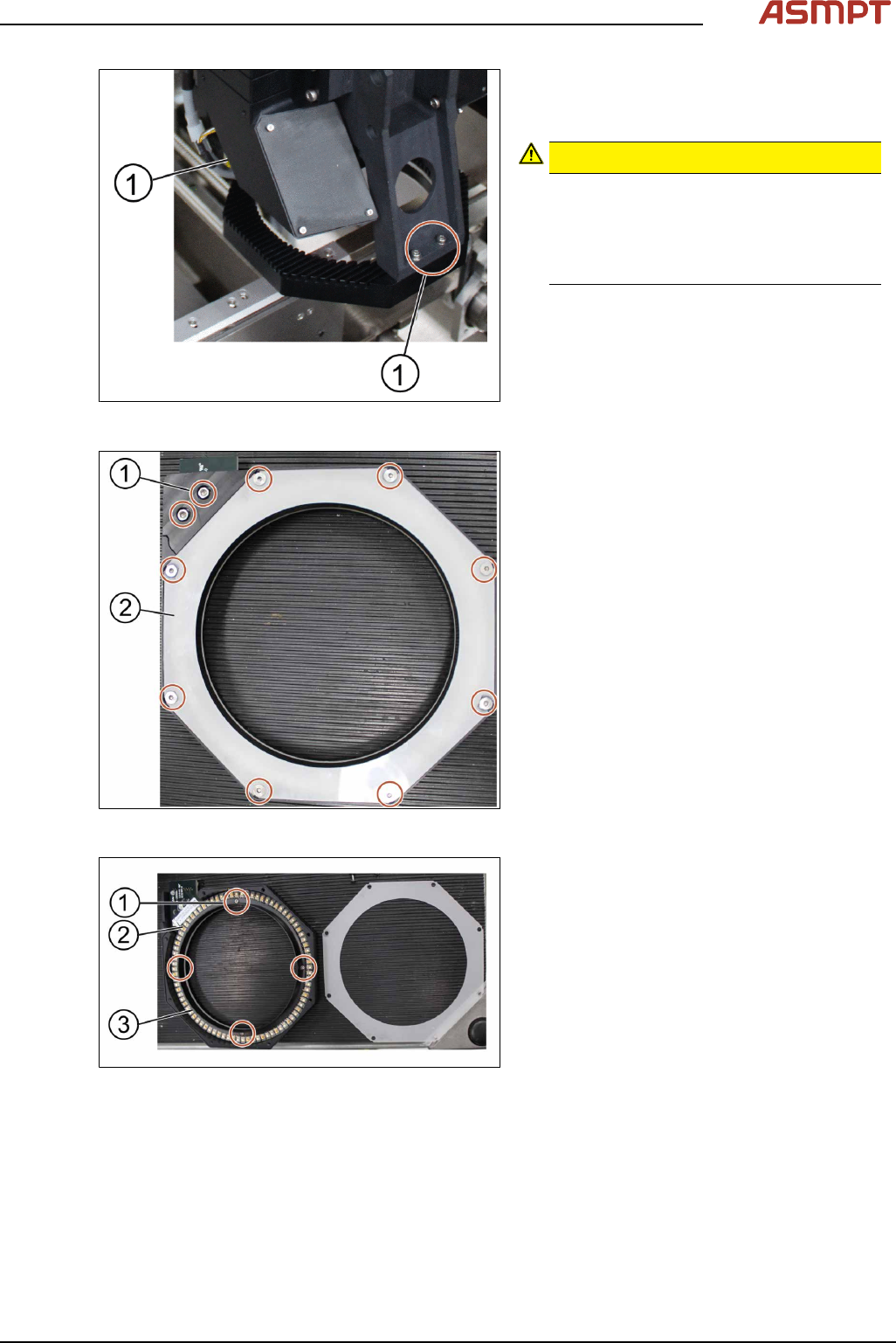
Fig.10: Removing the screws
► Remove the four screws (1) on the low
ring light assembly using an Allen key size
2.5.
CAUTION!
Different types of screws
There are two different types of screws.
The ones in the back are shorter than the
ones in the front.
Do not interchange the screws.
.
► Remove the low ring light assembly and
place it on a service table.
Fig.11: Removing all screws
► Remove all screws (1) with an Allen key
size 2.5.
► Remove the cover (2) of the low ring light
assembly.
Fig.12: Removing the low ring light board
► Remove the screws (1) using a Philips
screwdriver.
► Remove the plastic ring (3) and place it on
the service table.
► Remove the low ring light board (2).
Installation
Follow the removal instructions in reverse order for installation.
3 Replacing spare parts
26 Service Manual Process Lens PL - 03/2025
3.1.1.3 Replacing the high ring light board
Parts
03122924-xx High ring light board
Equipment and tools
●
Allen key size 1.5
●
Allen key size 2.5 (T shaped)
●
Philips screwdriver
Requirements
●
Machine is switched off.
●
It is advisable to dismantle the low ring light assembly as well for better access.
●
Use a T shaped Allen key to carry out this task.
Removal
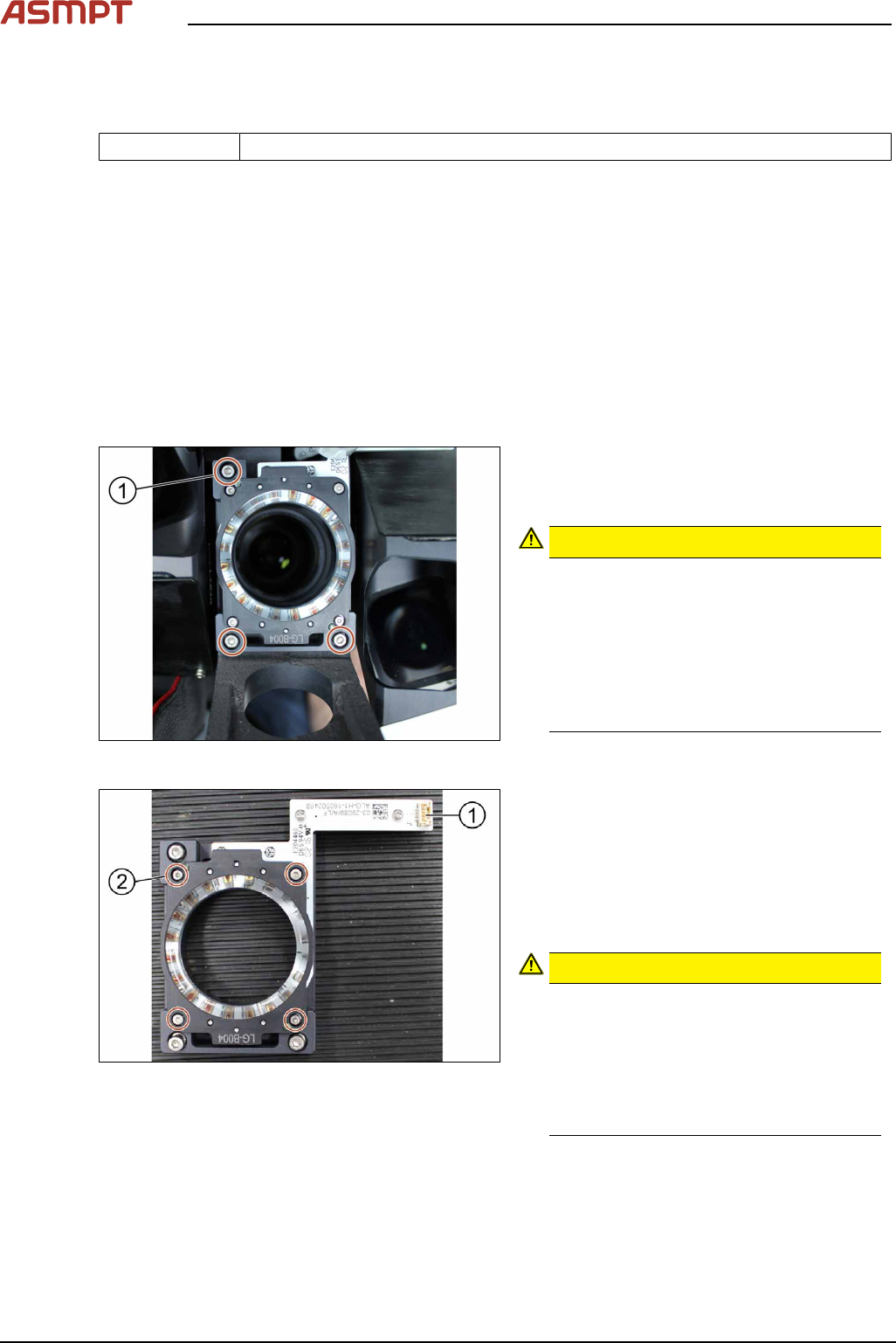
Fig.13: Removing the screws
► Unplug the connector
► Remove the three screws (1) using an
Allen key size 2.5.
CAUTION!
Small screws
The screws are very small. When the
screws fall into the machine they may
damage it.
Make sure the screws don’t fall into the
machine.
Make sure no screw is left behind inside
the machine.
.
Fig.14: Removing the connector
1. Connector
2. Screw (4 x) and washers (4 x)
► Remove the four screws (2) using an Allen
key size 1.5.
► Remove the four washers.
► Separate the high ring light assembly.
CAUTION!
Ring light assembly
The two parts of the ring light assembly
are hold together by two dowel pins.
When separating the two parts the ring
light assembly may get damaged.
To separate the two parts, carefully pull
the parts apart.
.
3 Replacing spare parts
Service Manual Process Lens PL - 03/2025 27
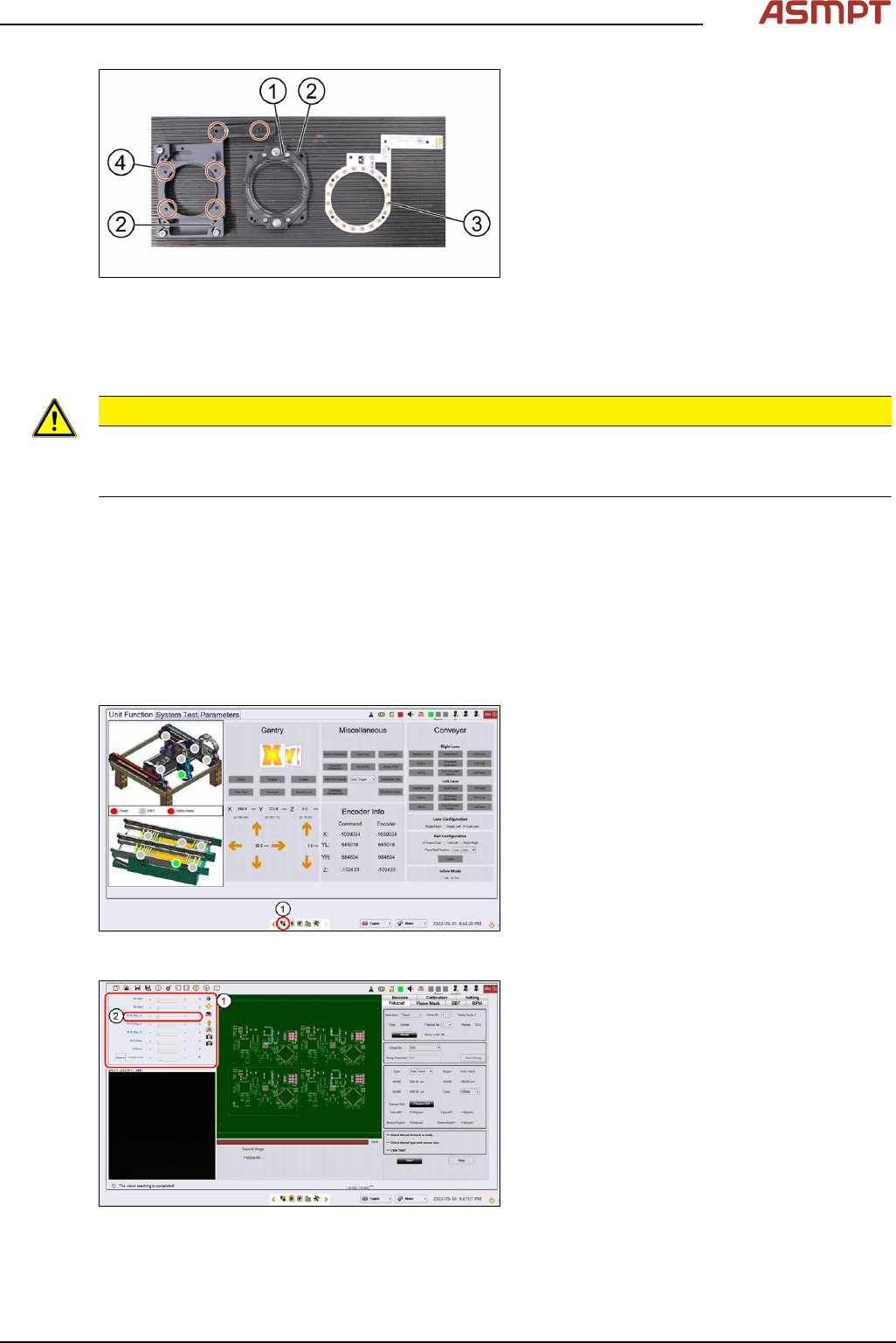
Fig.15: Removing the high ring light board
1. High ring light assembly
2. Dowel pin
3. High ring light board
4. Screws
► Remove the six screws(4) that hold the
high ring light board(3) in place using a
Philips screwdriver.
► Remove the high ring light board(3).
Installation
Follow the removal instructions in reverse order for installation. Also observe the following instructions.
CAUTION
Do not overtighten the screws
When the high ring light board is reassembled, one must not overtighten the screws, as this may
damage the high ring light board.
3.1.1.4 Checking the function of the low ring light and the high ring light
Requirements
●
Machine is switched on.
●
Machine doors are open.
●
The low ring light and the high ring light are mounted.
Checking the function
Fig.16: Control button
► Go to the diagnostic pages and press the
control button(1).
Fig.17: Lighting control page
► On the Lighting control page click on the
lighting control button.
► The Lighting box(1) is displayed.
► In the 2D Lighting Setup section push the
slider to the right.
► Starting with slider bar M-Ring_G(2)
check the green light of the low ring light.
► Check if all LEDs are functional and flash-
ing by using a mirror or view from under-
neath the optical head.
► Approach the same for all other slider bars
in that section.