Process Lens PL Service Manual_EN.pdf - 第92页
3 Replacing spare parts 92 Se rv ic e Ma nu al P ro ce ss L en s PL - 0 3/ 20 25 3.5.1.6 Fiber optic cables and laser light barriers Replacing the laser light barrier for the transmitter/receiver Parts Fig.124: Laser li…
3 Replacing spare parts
Service Manual Process Lens PL - 03/2025 91
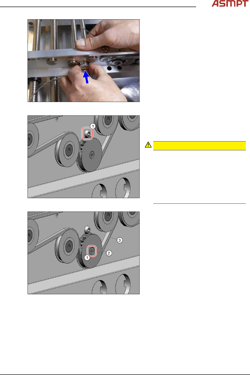
Fig.121: Inserting the pinion gear drive
► Insert the pinion gear drive.
Fig.122: Screw
► Secure the pinion gear drive with the
screw(1) (Allen, DIN EN ISO 7380-M3x4-
A2-70 [03074775‑xx]). Tighten the screw
with a torque of 0.58Nm.
CAUTION!
Make sure that you do not tighten the
screw too much. This could cause irre-
parable damage to the conveyor!
The corresponding threads are only in 1.5
to 2mm thick plates and could be dam-
aged if you use a torque which is too high.
For this reason, avoid using screws which
are too short. Use a measuring scale to
check, if needed!
.
Fig.123: Screw
► Thread in the toothed belt(3).
Make sure that the toothed belt is posi-
tioned accurately in the guidance on the
motor shaft or in the belt drive.
► Fix the washer(2) with the screw(1)
(cross head).
► When you tighten the idler pulley, set the tension of the toothed belt.
Setting the tension of the conveyor toothed belt
3 Replacing spare parts
92 Service Manual Process Lens PL - 03/2025
3.5.1.6 Fiber optic cables and laser light barriers
Replacing the laser light barrier for the transmitter/receiver
Parts
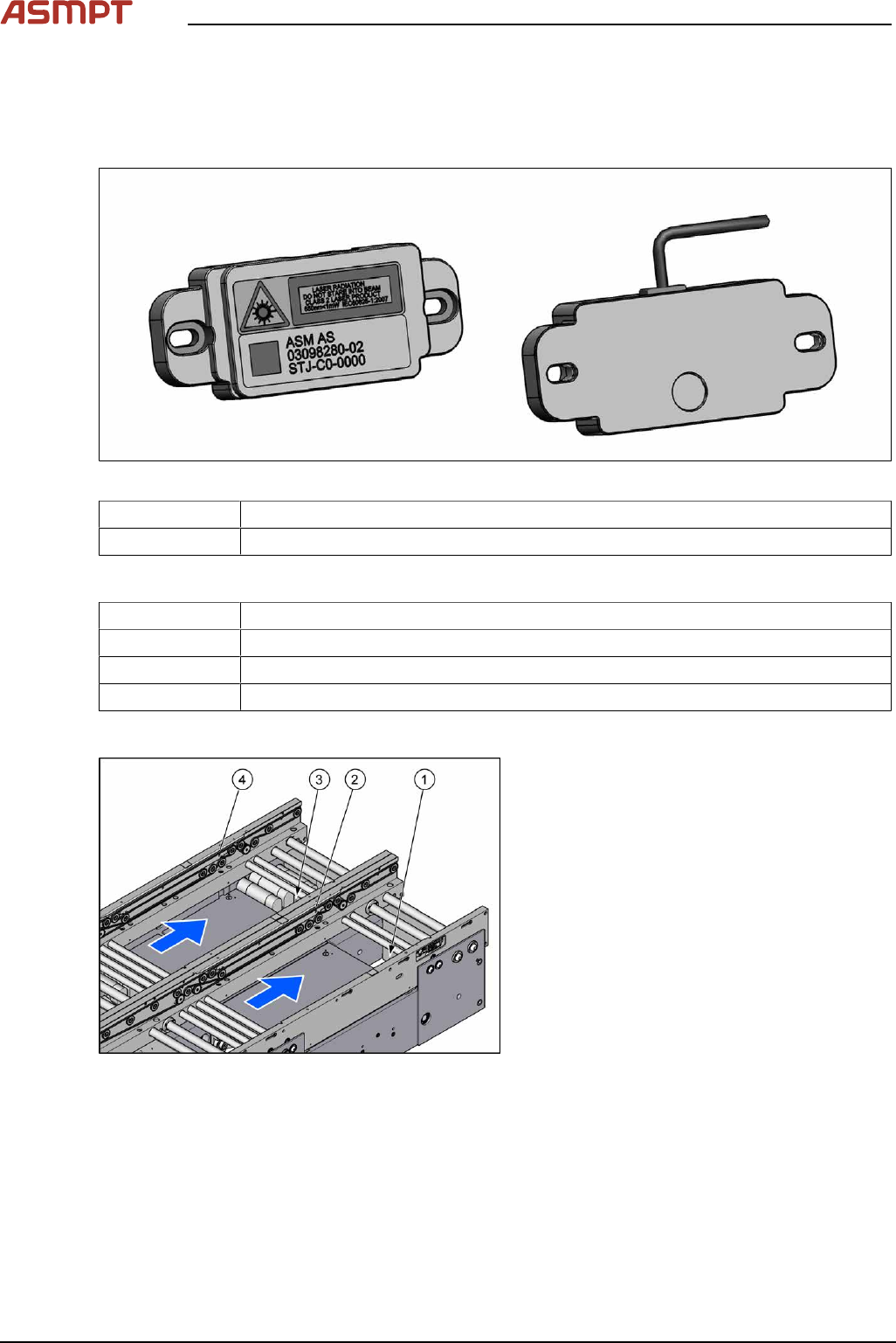
Fig.124: Laser light barrier transmitter and receiver
03098280‑xx Laser light barrier transmitter
03098281‑xx Laser light barrier receiver
Equipment and tools
00353832-xx Allen key set
Flash light
Magnet lifter
Tweezers
Overview
Fig.125: Transmitter and receiver
1. Transmitter PA (track 1)
2. Receiver PA (track 1)
3. Transmitter PA (track 2)
4. Receiver PA (track 2)
3 Replacing spare parts
Service Manual Process Lens PL - 03/2025 93
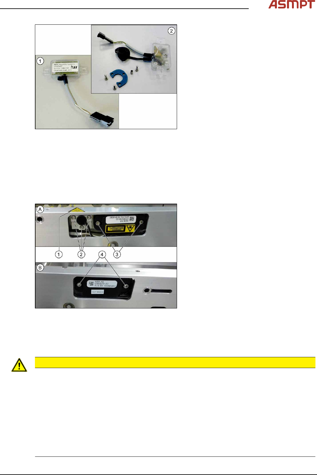
Fig.126: Transmitter and receiver
1. Receiver
2. Transmitter (incl. assembly material)
Removal
► Use the software or manually move the conveyor rail into a position which allows you best
access.
To move the conveyor side wall manually, pull the toothed belt of the width adjustment unit.
► Switch off the machine, disconnect it from the power supply and secure it to prevent unauthorized
reactivation.
Fig.127: Removing transmitter and receiver
The transmitters are always near the laser
warning labels(1). The receivers are always on
the opposite rails.
► (A) Transmitter:
Remove the five fastening screws(2)
and(3). Make sure that no parts fall into
the conveyor rail.
► (B) Receiver:
Remove the two fastening screws(4).
Make sure that no parts fall into the con-
veyor rail.
► Unplug the electrical connection.
Installation
► Follow the removal instructions in reverse order for installation. Also observe the following
instructions:
CAUTION
Installation instructions
► Reconnect the transmitter/receiver before installation.
► Make sure that all the other cables in the conveyor rail are run under the transmitter/receiver.
There is a particular lack of space at the transmitters.
► Use the bushing for the bottom screw. This screw is used to fix the sensor.
The two upper screws are used to adjust the laser beam.
► The transmitters are fixed hand-tight with the lower screw and adjusted with the top two screws.
► Check the setting for the transmitter / receiver and correct it if necessary (see 3.5.1.6.4.1 "Setting
the fiber optic sensor" [}101]).
► Teach the PCB sensors using the station software (see Teaching the PCB sensors (SW70x)).