Process Lens PL Service Manual_EN.pdf - 第121页
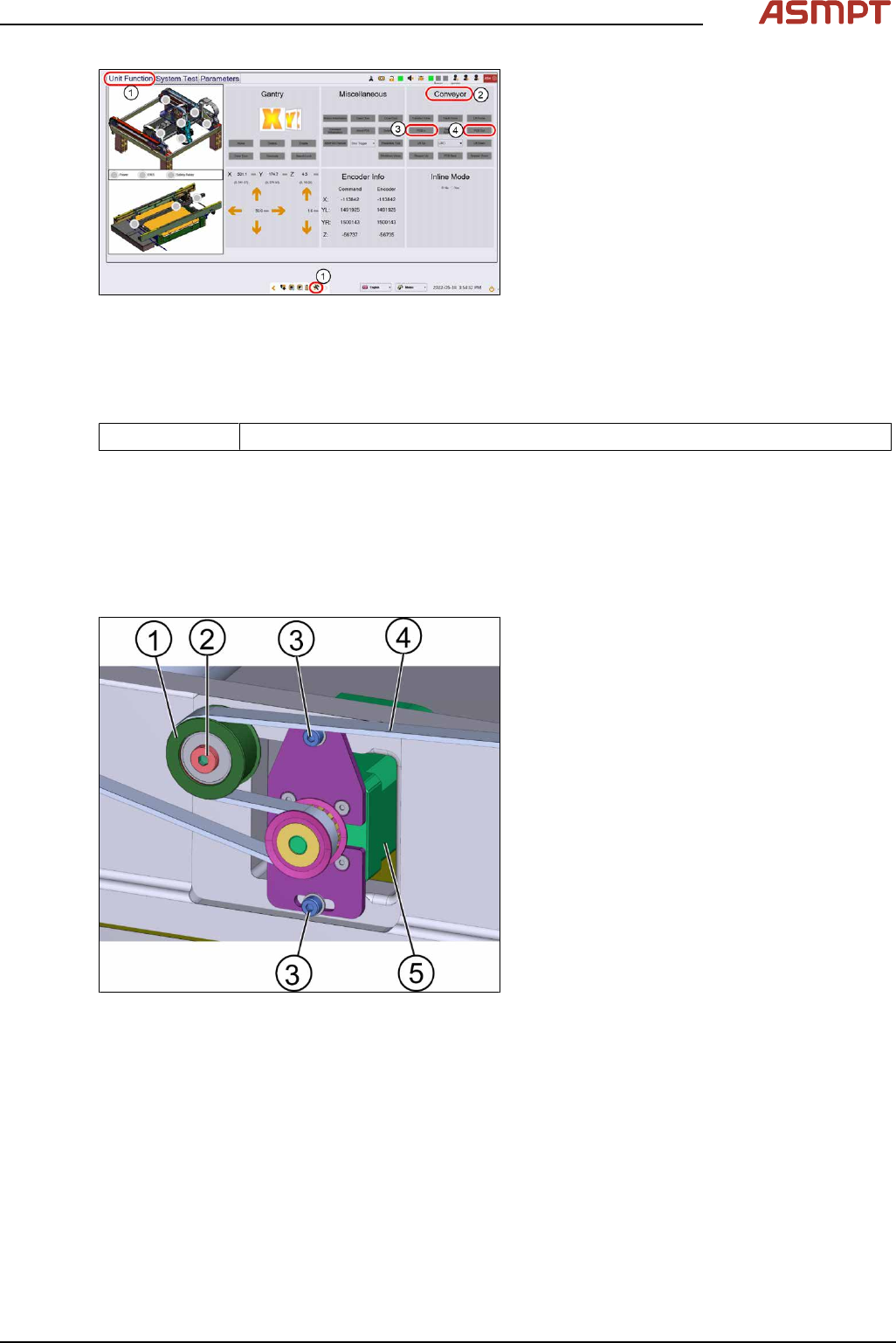
3 Replacing spare parts Se rv ic e Ma nu al P ro ce ss L en s PL - 0 3/ 20 25 12 1 Fig.168: “Unit function” tab ► Go to the diagnostic page. ► Click on the tab Unit function (1) . ► Go to the section Conveyor (2) . ► …
3 Replacing spare parts
120 Service Manual Process Lens PL - 03/2025
Fig.166: Conveyor motor (from back)
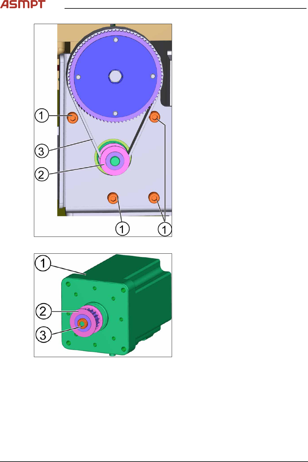
► Unscrew the 4 screws(1) using an Allen
Key size 4.0.
► Take off the conveyor motor belt(3).
► Take out the motor of the machine.
Fig.167: Conveyor motor
► Unscrew the screw(3) off the gear(2) of
the old motor(1) and replace it onto the
new motor using an Allen Key size 4.0.
► Put the motor back in place.
► Put the belt on and tighten the screws.
► Connect the connectors to the TSP400.
Installation
Follow the removal instructions in reverse order for installation.
Check the function of the conveyor motor
Requirements
●
Machine is switched on.
●
Circuit board is placed at the beginning of the machine.
3 Replacing spare parts
Service Manual Process Lens PL - 03/2025 121
Fig.168: “Unit function” tab
► Go to the diagnostic page.
► Click on the tab Unit function(1).
► Go to the section Conveyor(2).
► Click the button PCB In(3) and the button
PCB Out(4).
► If the circuit board cannot move through
the machine the conveyor system needs
to be adjusted.
3.5.2.3 Changing the width adjustment belt
Parts
03106079-xx WA brecoflex timing belt 10T5/1700
Equipment and tools
●
Allen key size 3.0
Requirements
●
Machine is switched off.
●
Tension meter.
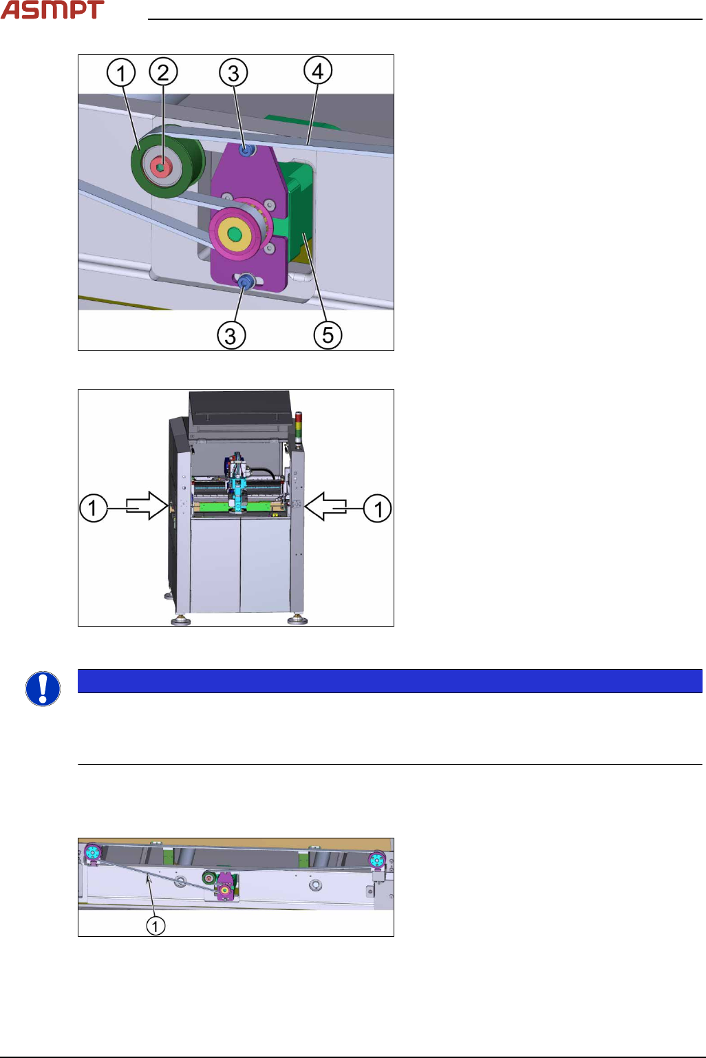
Fig.169: Motor for the width adjustment
1. Tension ring
2. Screw A
3. Screw B (2 x)
4. Belt
5. Motor
► Loosen the tension ring by loosen the
screw A(2).
► Remove the motor by loosen the screws
B(3) using an Allen key size3.
► Remove the belt(4) and replace it with a
new one.
Assembling of the width adjustment belt
Requirements
●
Machine is switched off.
●
Tension meter.
●
Tension ring is loosened.
●
Inspection circuit boards (2 x).
3 Replacing spare parts
122 Service Manual Process Lens PL - 03/2025
Fig.170: Motor for the width adjustment
1. Tension ring
2. Screw A
3. Screw B (2 x)
4. Belt
5. Motor
► Put the width adjustment belt(4) in posi-
tion.
► Place the two inspection circuit boards
between the two conveyor systems.
Fig.171: Machine
1. Position of the inspection circuit boards
NOTICE
Alignment of the conveyor units
The distance between the two conveyor units need to allow the inspection circuit boards to pass
through with ease. For that the width of the conveyor units need to be parallel to each other. The in-
spection circuit boards help to achieve the alignment of the conveyor units.
► Fasten the tension ring.
► Check whether the boards can move through the conveyer systems with ease. If not adjust the
width adjustment belt.
Fig.172: Width adjustment belt
► Check the tension of the width adjustment
belt at the measurement point(1) using a
tension meter.
► The tension should be 60 +/- 6 Hz.