Process Lens PL Service Manual_EN.pdf - 第91页
3 Replacing spare parts Se rv ic e Ma nu al P ro ce ss L en s PL - 0 3/ 20 25 91 Fig.121: Inserting the pinion gear drive ► Insert the pinion gear drive. Fig.122: Screw ► Secure the pinion gear drive with the screw (1…
3 Replacing spare parts
90 Service Manual Process Lens PL - 03/2025
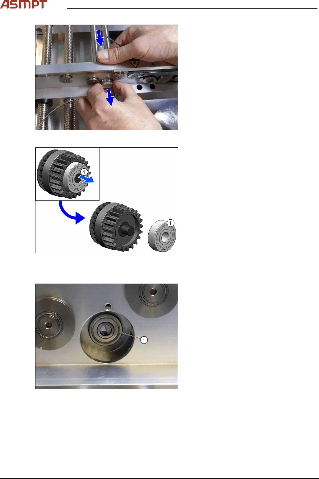
Fig.118: Pulling out the pinion gear drive
► From the rear of the rail, push the pinion
gear drive out.
Fig.119: Pulling off the bearing
► Pull the bearing(1) off the pinion gear
drive.
Installation
Fig.120: Inserting the bearing
► Insert the bearing(1) into the rail.
Make sure that the bearing does not fall
into the rail.
3 Replacing spare parts
Service Manual Process Lens PL - 03/2025 91
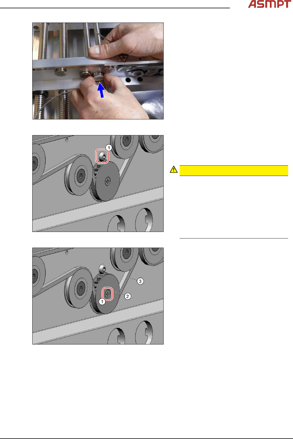
Fig.121: Inserting the pinion gear drive
► Insert the pinion gear drive.
Fig.122: Screw
► Secure the pinion gear drive with the
screw(1) (Allen, DIN EN ISO 7380-M3x4-
A2-70 [03074775‑xx]). Tighten the screw
with a torque of 0.58Nm.
CAUTION!
Make sure that you do not tighten the
screw too much. This could cause irre-
parable damage to the conveyor!
The corresponding threads are only in 1.5
to 2mm thick plates and could be dam-
aged if you use a torque which is too high.
For this reason, avoid using screws which
are too short. Use a measuring scale to
check, if needed!
.
Fig.123: Screw
► Thread in the toothed belt(3).
Make sure that the toothed belt is posi-
tioned accurately in the guidance on the
motor shaft or in the belt drive.
► Fix the washer(2) with the screw(1)
(cross head).
► When you tighten the idler pulley, set the tension of the toothed belt.
Setting the tension of the conveyor toothed belt
3 Replacing spare parts
92 Service Manual Process Lens PL - 03/2025
3.5.1.6 Fiber optic cables and laser light barriers
Replacing the laser light barrier for the transmitter/receiver
Parts
Fig.124: Laser light barrier transmitter and receiver
03098280‑xx Laser light barrier transmitter
03098281‑xx Laser light barrier receiver
Equipment and tools
00353832-xx Allen key set
Flash light
Magnet lifter
Tweezers
Overview
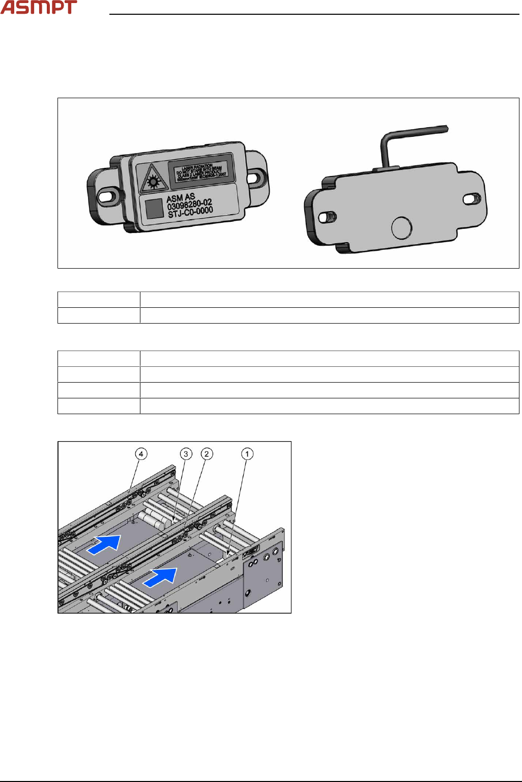
Fig.125: Transmitter and receiver
1. Transmitter PA (track 1)
2. Receiver PA (track 1)
3. Transmitter PA (track 2)
4. Receiver PA (track 2)