Process Lens PL Service Manual_EN.pdf - 第98页
3 Replacing spare parts 98 Se rv ic e Ma nu al P ro ce ss L en s PL - 0 3/ 20 25 Further installation is performed by following the above instructions in the reverse order. Also observe the following instructions: ► Chec…
3 Replacing spare parts
Service Manual Process Lens PL - 03/2025 97
NOTICE
Sticker
If the fiber optic cable has already been repaired, a yellow adhesive sticker dot will be attached to the
optical system or the fiber optic sensor.
One repair hose may be used per fiber optic cable. You must either replace the whole fiber optic
cable or the part that has already been repaired.
► Check the fiber optic cable for damages.
The most common error causes are:
– Optical system of the fiber optic cable damaged
– Fiber optic cable pinched in conveyor side
– Fiber optic cable ruptured (e.g. caused by a too narrow bending radius)
NOTICE
Fiber optic cable ruptured at the trailing chain
If the fiber optic cable is ruptured in the trailing chain or at the transition from the trailing chain to the
conveyor side, the effort for finding the error cause is often identical to the effort for replacing the
complete fiber optic cable.
► Cut the fiber optic cable at the defective position.
► Use the cutter tool to cut off 10mm of the fiber optic cable on each side of the rupture.
Make sure to preserve a minimum distance of approx. 50mm to the optical system of the fiber
optic cable.
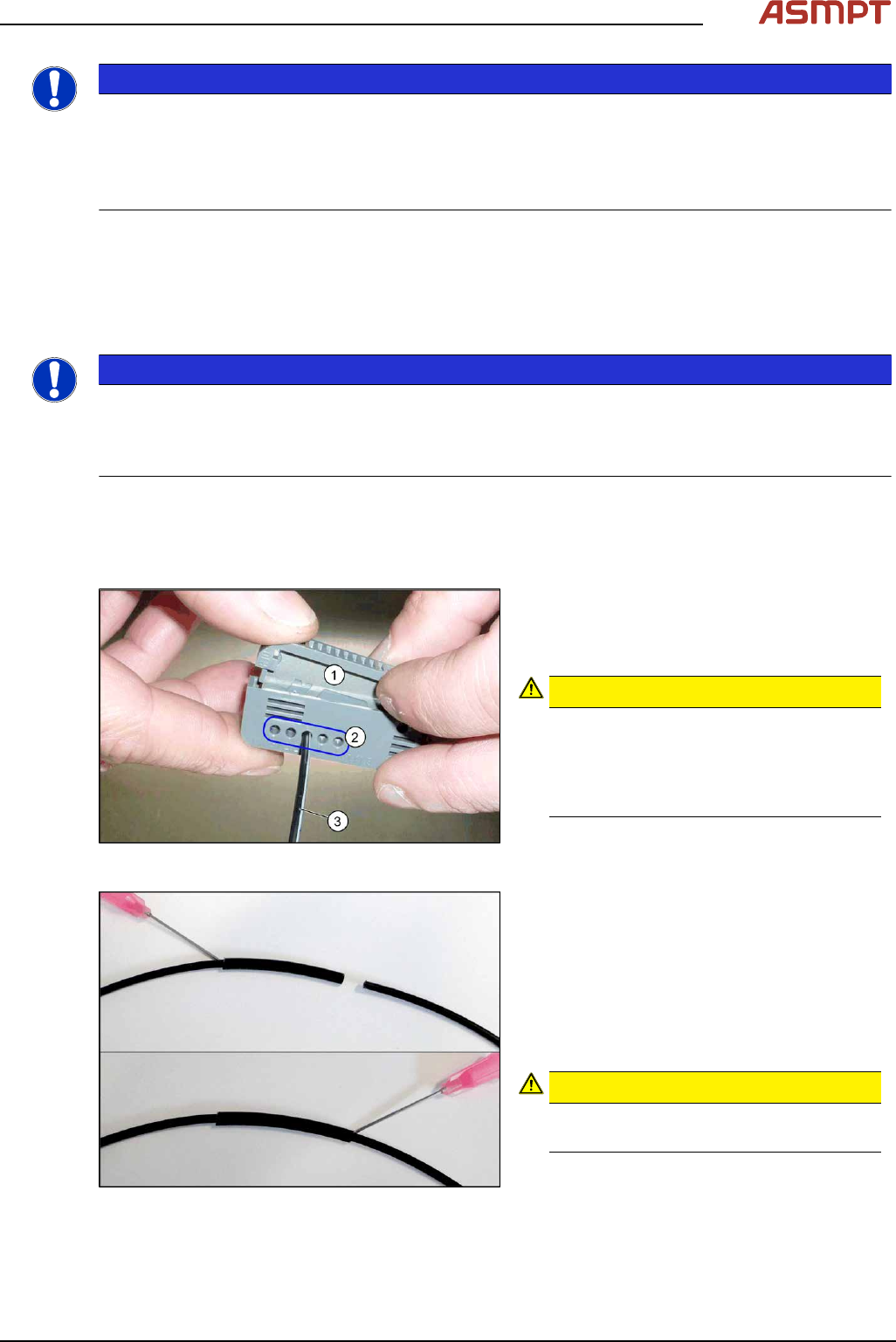
Fig.131: Cutter tool
1. Cutter tool
2. Cutter openings
3. Fiber optic cable
CAUTION!
Only use each cutter opening once
Make sure that each cutter opening is
only used once. The quality of the cut
cannot be guaranteed if it is used more
than once.
.
Fig.132: Repairing the fiber optic cables
► Slide both ends of the fiber optic cable into
the repair hose until they touch each other.
► Fix the repair hose into place with Loctite
406.
This adhesive is used to fix the fiber optic
cable in the hose. The two ends of the
fiber optic cable are not fixed to one
another with adhesive.
CAUTION!
Highly viscous instant glue
Use gloves and a dosage tip.
.
3 Replacing spare parts
98 Service Manual Process Lens PL - 03/2025
Further installation is performed by following the above instructions in the reverse order. Also observe
the following instructions:
► Check the setting for the transmitter/receiver and correct if necessary.
► Calibrate the sensors of the PCB conveyor.
► Check the display on the fiber optic sensor. The value shown must be over 100. Check the value
for the various conveyor widths (red = output / green = input).
► Mark the optical system and the fiber optic cable at the fiber optic sensor with the glue dot sup-
plied. The glue dot indicates that the fiber optic cable has already been repaired and that a re-
placement is compulsory at the next defect.
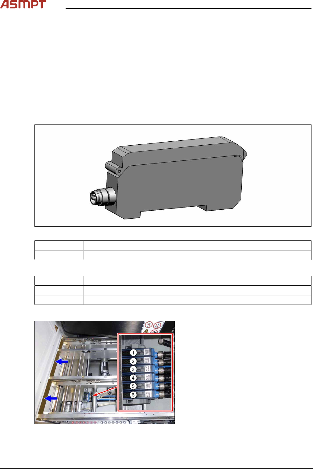
Replacing the fiber optic sensor
Parts
Fig.133: Fiber optic sensor
03093294-xx Fiber optic sensor WLL180T-M pre-programmed SXa (master)
03093295-xx Fiber optic sensor WLL180T-F pre-programmed SXa (slave)
Equipment and tools
00353832-xx Allen key set
Side cutter
Cable ties
Overview
Fig.134: Fiber optic sensors
The fiber optic sensors are located at location 2
under the lifting table plate.
(1) to (6): fiber optic sensors for the input area,
placement area and output area.
The receivers are always at the top of the fiber
optic sensors and the transmitters at the bot-
tom.
3 Replacing spare parts
Service Manual Process Lens PL - 03/2025 99
Conveyor track Designation Description
Track 1 1 (slave) Output area
2 (slave) Inspection area
3 (slave) Input area
Track 2 4 (slave) Output area
5 (slave) Inspection area
6 (master) Input area
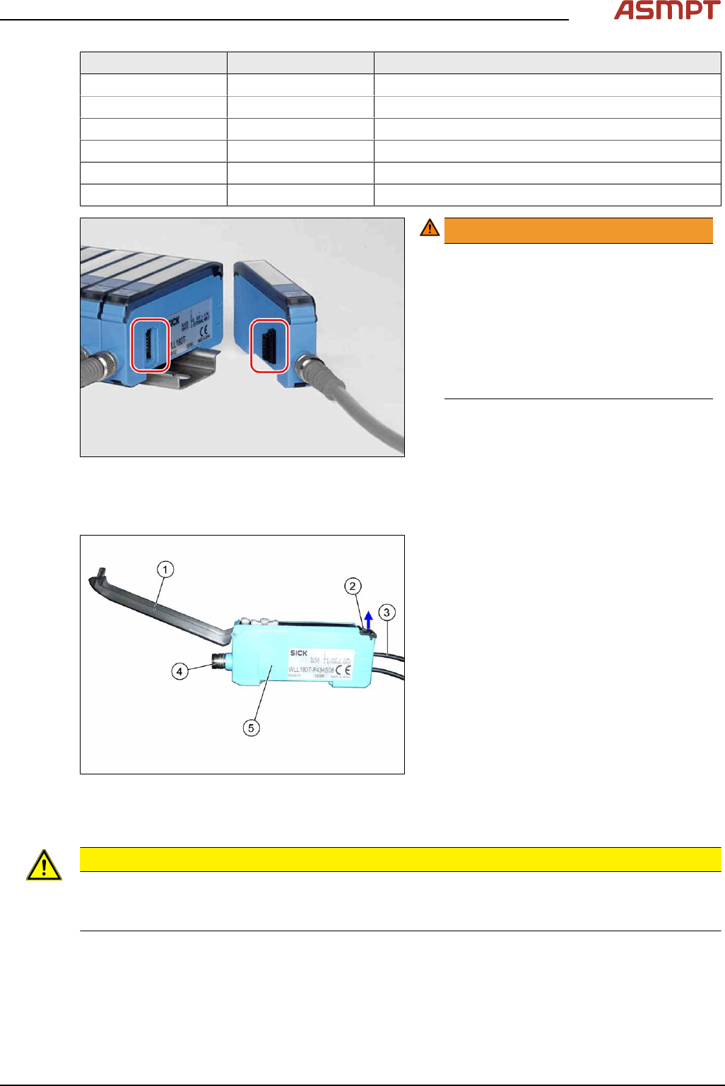
Fig.135: Plug-and-socket connections
WARNING!
The adjacent fiber optic sensors are
connected via plug-and-socket con-
nections on the side.
Before dismantling the fiber optic sensors
always separate them a bit.
Do not lift the fiber optic sensors off
without separating them first. If you do so,
you may damage the plug-and-socket
connection.
.
Each sensor has two fiber optic cables connected (transmitter/receiver), which belong to the same
conveyor belt (segment).
Fig.136: Fiber optic sensor
1. Cover
2. Locking the fiber optic cables
top = open
bottom = closed
3. Fiber optic cable
Top: input (from receiver)
Bottom: output (to transmitter)
4. Electrical connection
5. Electrical connection to neighboring fiber
optic sensor (under the plastic cover)
Removal
CAUTION
Do not bend fiber optic cables
► Make sure you do not bend the fiber optic cables. Otherwise the cable will become cloudy and
no longer transmit the signal properly.
► Use the software or manually move the conveyor rail into a position which allows you best
access.
To move the conveyor side wall manually, pull the toothed belt of the width adjustment unit.
► Switch off the machine, disconnect it from the power supply and secure it to prevent unauthorized
reactivation.