Process Lens PL Service Manual_EN.pdf - 第83页
3 Replacing spare parts Se rv ic e Ma nu al P ro ce ss L en s PL - 0 3/ 20 25 83 Equipment and tools 00326015‑xx Belt tension measuring device 00353832-xx Allen key set 03082092-xx Lint-free cleaning cloths Ethanol Isopr…
3 Replacing spare parts
82 Service Manual Process Lens PL - 03/2025
CAUTION
Do not let the T groove nut fall into the conveyor rail!
► Do not remove the movable idler pulley completely, to make sure that the grooved nut does not
fall into the conveyor rail.
► Repeat the measurement four times.
Calculating the belt tension
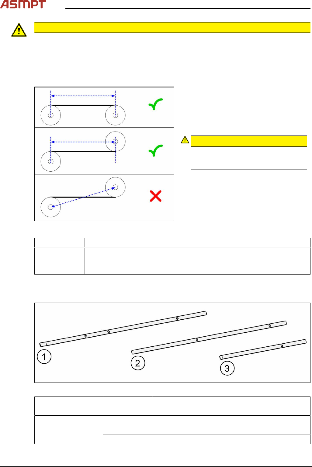
Fig.108: Measuring the distance
► Define the two idler pulleys between which
you want to set the belt tension. If pos-
sible, do not use the movable idler pulleys.
► Measure the distance between the two
idler pulleys parallel to the conveyor
belt. (See diagram)
CAUTION!
Note that it is not always possible to
simply measure the distance between the
idler pulleys from center to center.
.
► Calculate the belt tension using the follow-
ing formula:
(15000 / idler pulley spacing [mm]) [Hz]
The permissible tolerance is always plus/minus
10% of the calculated value.
Example Distance between the idler pulleys: 235mm
Calculation 15000 / 235 = 64 (rounded, exactly 63.829…)
10 % von 63.829… = 6 (rounded, exactly 6.3829…)
Result → Belt tension: 64 +/- 6 Hz
Replacing the side sheet metal plates
Parts
Fig.109: Side sheet metal plates
1 Input area 03132184Sxx Side sheet metal plate 7x1x399,25 EB BB RC
2 Inspection area 03132182Sxx Side sheet metal plate 7x1x370,5 EB BB RC
3 Output area 03132183Sxx Side sheet metal plate 7x1x205,5 AB RC
Each included in scope
of delivery:
03154789-xx Tape double-sided B = 6 + 1mm
03154790-xx Tape double-sided B = 6 + 1mm, electrically conductive

3 Replacing spare parts
Service Manual Process Lens PL - 03/2025 83
Equipment and tools
00326015‑xx Belt tension measuring device
00353832-xx Allen key set
03082092-xx Lint-free cleaning cloths
Ethanol
Isopropanol – IPA can be used as an alternative.
Removal
CAUTION
Do not loosen the wrong screws
Make sure that you do not loosen any other screws except those ones explicitly mentioned. Loosen-
ing other screws could lead to irreparable misalignment or damage to the conveyor.
► Use the software or manually move the conveyor rail into a position which allows you best
access.
To move the conveyor side wall manually, pull the toothed belt of the width adjustment unit.
► Switch off the machine, disconnect it from the power supply and secure it to prevent unauthorized
reactivation.
► Remove the relevant toothed belt.
Replacing the toothed belt (conveyor belt)
► Pull the old side sheet metal plate off the conveyor rail.
Installation
► Clean the adhesive surfaces on the conveyor rail.
3 Replacing spare parts
84 Service Manual Process Lens PL - 03/2025
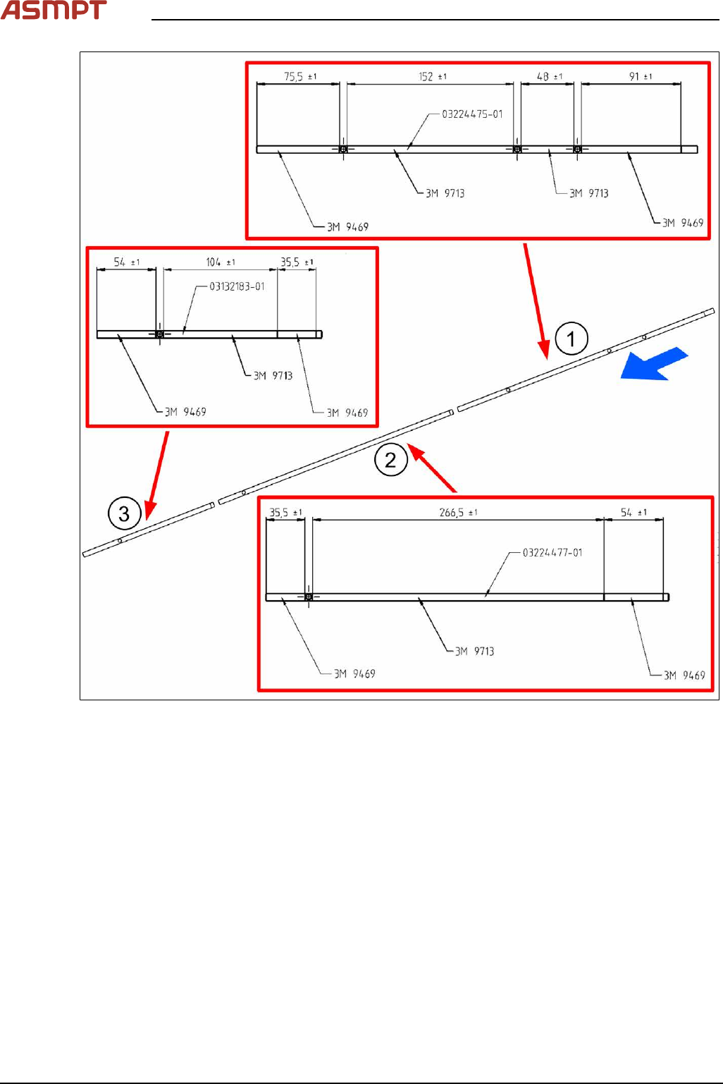
Fig.110: Attaching the adhesive tapes
► Attach the adhesive tapes to the side sheet metal plates as described in the figure. Observe the
following points:
●
In the input area(1) towards the outside of the machine, electrically conductive adhesive tape
3M-9469 [03154790-xx] is applied on a 91mm wide stripe.
●
In the placement area(2), the electrically conductive adhesive tape is not used.
●
In the output area(3) towards the outside of the machine, a 54mm wide stripe is applied with
electrically conductive adhesive tape 3M-9469 [03154790-xx].
●
The other surfaces of the sheet metal plates are not applied with electrically conductive tape
3M-9713 [03154789‑xx]. Make sure to keep the holes for the light barriers free.