DECAN_S2_Admin(Eng_Ver4.5).pdf - 第105页
4-24 Advanced Chip Shooter DECAN S2 Admi nistra t or’s Guide Ref. Once the value of the teaching of the deleted Z column can not be undone. <Of f set Check> group <He ad> c o mbo box Selects the head to m…
4-23
Tools Shortcut Menu
<Position> group
<Light> button
Outer
Adjusts the outer lighting for the Down Camera of the selected Gantry.
Inner
Adjusts the inner lighting for the Down Camera of the selected Gantry.
<Move> button
Move the fiducial camera of the selected gantry.
<Get> button
Applys the coordinate value of the current position as the selected fiducial
mark position.
<PrevMove> button
The fiducial camera moves from the current position to the previous position.
<NextMove> button
The fiducial camera moves from the current position to the next position.
<InitialXY> group
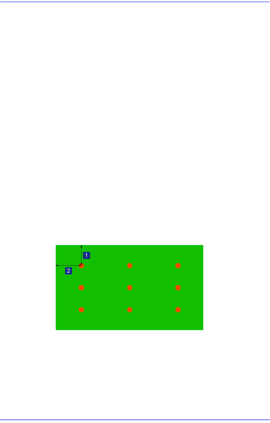
<MarginX> editbox
Refers to the margin in the X direction of the board.
<MarginY> editbox
Refers to the margin in the Y direction of the board.
1: MatginY
2: MarginX
<Clear> button
Deletes the teaching values of the Z-column in the <Spread> group.
4-24
Advanced Chip Shooter DECAN S2 Administrator’s Guide
Ref. Once the value of the teaching of the deleted Z column can not be
undone.
<Offset Check> group
<Head> combo box
Selects the head to measure the board flatness.
<PrevDetect / NextDetect> button
<PrevDetect> button: Measures the previous coordinate value of the
coordinate currently selected in the <Spread> group.
<NextDetect> button: Measures the next coordinate value of the coordinate
currently selected in the <Spread> group.
Ref. The <PrevDetect / NextDetect> button is enabled when the
<Manual> check box is selected.
<Manual> check box
Teach the Z values at the X and Y coordinates manually using the
<PrevDetect / NextDetect> button.
<Detect Z> button
Teach the Z value for the X and Y coordinates of the cell currently selected in
the <Spread> area.
<Automatic> check box
After selecting the Z column to be measured in the <Z> combo box, pressing
the <Detect Z> button will measure the Z column automatically.
4-25
Tools Shortcut Menu
4.7.2. Head Tab dialog box
Performs setup of camera lighting or check of head operation by manually recognizing
parts with vision system.
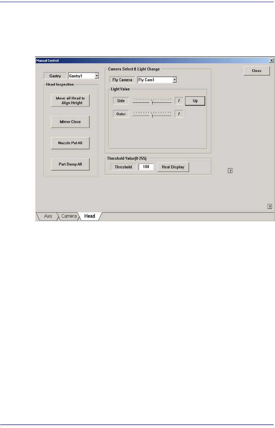
Figure4.8 “Manual Control – Head” dialog box
<Gantry> combo box
Select the gantry to which the head to be tested belongs.
<Head Inspection> group
<Move all head to align height> button
Put the nozzle tip of the head at the align height for parts recognition.
<Mirror Open/Close> button
Open or close the mirror for parts recognition.
<Nozzle Put All> button
Return all nozzles placed at the head to the ANC.
<Part Dump All> button
Dump all the picked up parts at the dump box.
<Camera Select & Light Change> group
Set the illumination value of the fly camera. Select the fly camera whose illumination
is to be adjusted and adjust the slide bar in the <Light Value> group to adjust the
brightness.