DECAN_S2_Admin(Eng_Ver4.5).pdf - 第399页
14-30 Advanced Chip Shooter DECAN S2 Ad ministra tor’s Guid e Displays the XY coordinates of the conveyo r fiducial mark set by the MMI. <Of f set (mm)> group Displays the Y value of the conveyor fiducial machine…
14-29
Machine Calibration
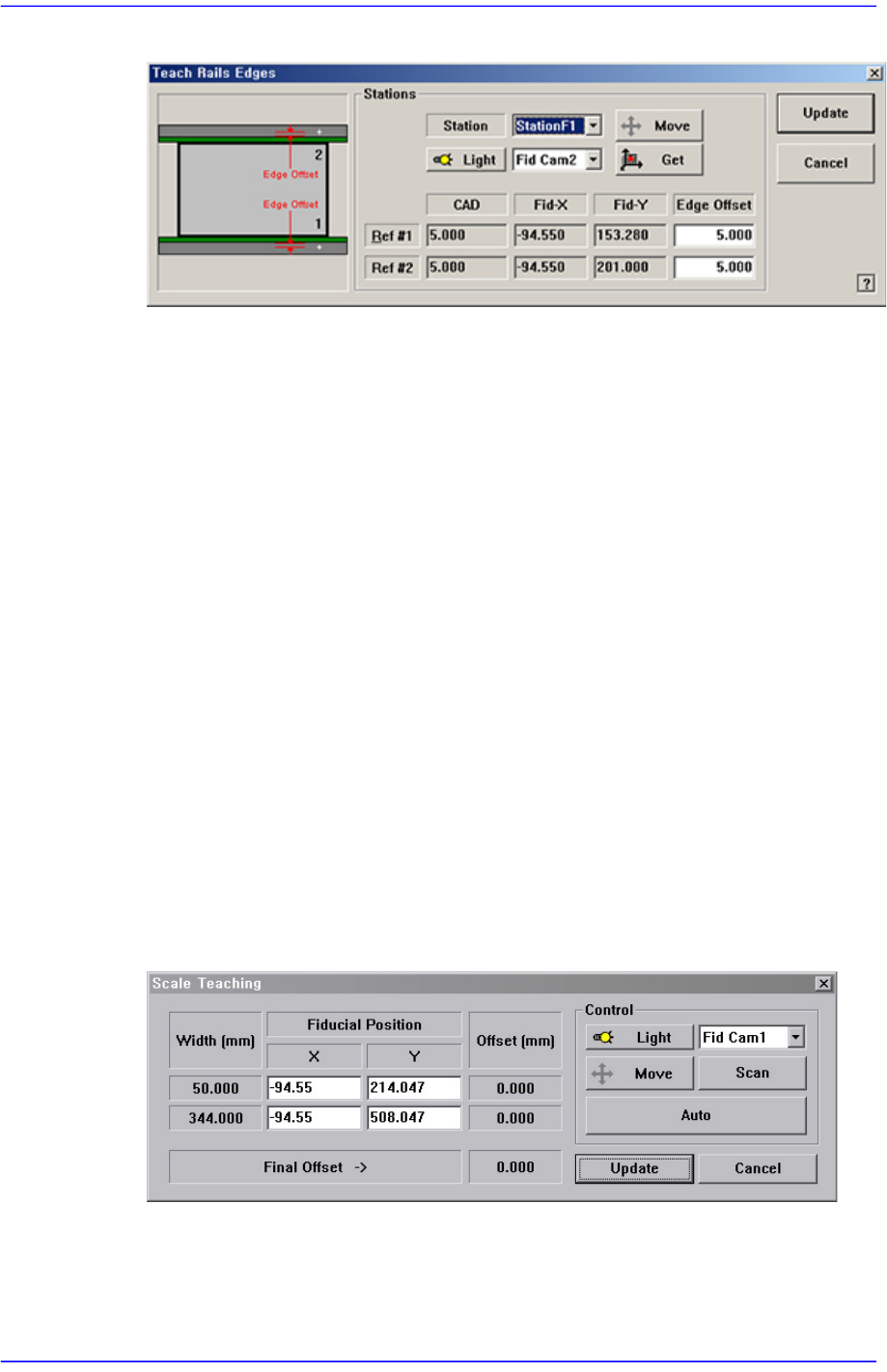
Figure14.10 “Teach Rails Edges” dialog box
<Edge Offset> edit box
Means the distance from the center of the fiducial mark to the edge of the rail.
Teaching must be performed after selecting this point using a mouse.
<Move> button
The <Move Cam> button can be clicked after first selecting a station and next
selecting the <Edge Offset> edit box. Then the downward camera (Fiducial
Camera) is moved to the center of the selected fiducial mark of the selected
station.
<Get> button
Apply the coordinate value of the current position as the selected fiducial mark
position.
<Light> button
Set the lighting value. Set the value by adjusting the sliding bar.
<Update> button
Applies the changed value and closes the dialog box.
<Scale Teach...> button
Teaches the Y offset of the conveyor fiducial mark.
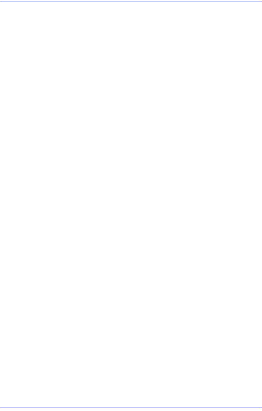
Figure14.11 “Scale Teach” dialog box
<Width (mm)> group
Displays the conveyor width provided by default for calibration.
<Fiducial Position> group
14-30
Advanced Chip Shooter DECAN S2 Administrator’s Guide
Displays the XY coordinates of the conveyor fiducial mark set by the MMI.
<Offset (mm)> group
Displays the Y value of the conveyor fiducial machine measured by the actual
machine as well as the offset of the Y value set by the MMI.
<Final Offset ->> group
A: Y offset when the conveyor width is 50mm
B: Y offset when the conveyor width is 344mm
Final Offset = B-A
<Move> Button
Moves the fiducial camera to the conveyor position selected from the <Fiducial
Position> group.
<Scan> Button
Scans the fiducial mark of the conveyor selected from the <Fiducial Position>
group and displays the Y offset in the <Offset (mm)> group.
<Auto> Button
Executes the Y offset teaching process of the conveyor fiducial mark
automatically.
<Light> Button
Sets the lighting value. Adjust the corresponding slide bar to set the lighting value.
<Update> Button
Applies changed values and closes the dialog box.
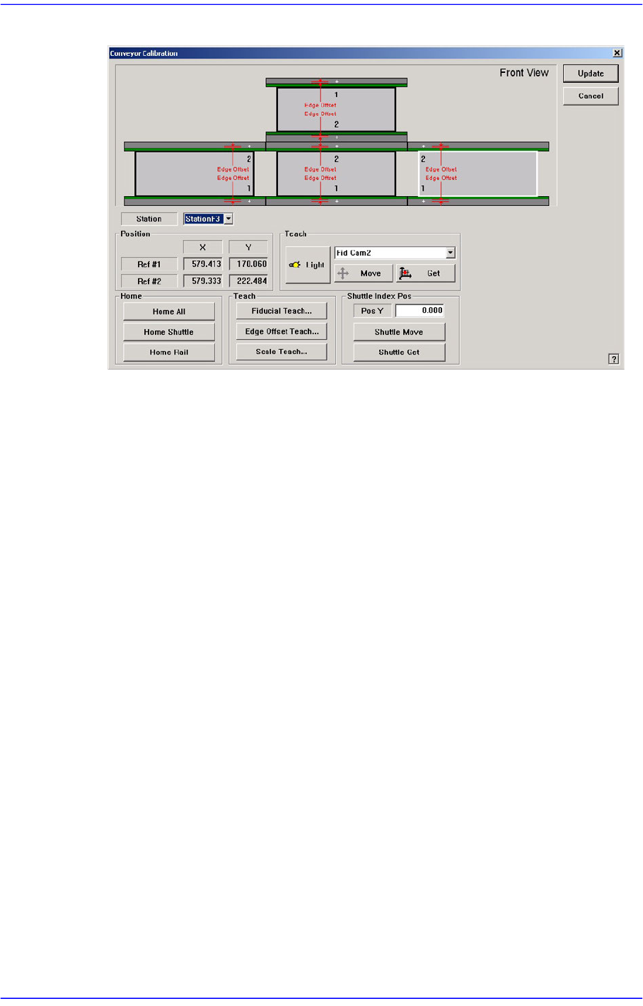
<Shuttle Index Pos> group
Provides the function that can adjust the outlet position of the exit shuttle if the
position of the fixed rail of the conveyor does not match with the discharge position of
the exit shuttle in the following equipment.
This function is enabled only when the ‘Home’ function is performed for the conveyor
rail after booting the equipment.
14-31
Machine Calibration
Figure14.12 "Conveyor Calibration-Shuttle Index Pos " dialog box
<Pos Y> edit box
Refers to the coordinate of the outlet position (index position) of the current exit
shuttle.
<Shuttle Move> button
Moves the shuttle to the position inputted in the <Pos Y> edit box. However, if the
rear rail is fixed, it moves the shuttle to the position less the width of the current
rail.
<Shuttle Get> button
Sets the current shuttle position as the coordinate of the machine. Move the exit
shuttle using the jog function of the teaching box to match it with the fixed rail of
the next machine, and click this button to input the coordinate of the shuttle index
position in the <Pos Y> edit box.
In the case of the equipment with fixed rear rail, adjust the conveyor width so that
it becomes identical to the conveyor width of the following equipment, and move
the exit shuttle to the position that allows PCB transfer between two equipments
using the jog function and then click this button to save the coordinate of the
shuttle index position. At this time, input the value obtained by adding the width
of the current rail to the current position in the <Pos Y> edit box.
[Setup Sequence of the Jog Function of the Teaching Box]
Jog → Conveyor → Station → Shuttle Axis