DECAN_S2_Admin(Eng_Ver4.5).pdf - 第193页
7-28 Advanced Chip Shooter DECAN S2 Admi nistra t or’s Guide recognition is greater than 0.1 it recognizes the angle after correcting the angle . It repeats this until the resul t of the recognition become less than 0.1.…
7-27
Part Registration
when setting 20%, actually apply 30%.
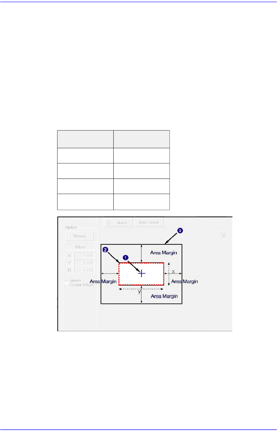
<Area Margin> edit box
If the area obtained by adding the Area Margin to the part size is called the ‘Part
Recognition Area’, in normal cases the shape of the picked part must be within the
‘Part Recognition Area’.
However, even though the shape of the picked part may get out of the ‘Part
Recognition Area’ due to other external factors, if the part can be placed properly
by compensating the offset, it is possible to place the corresponding part properly
by setting the ‘Allowable Error Range’
In general, set a value within the range of 0~6. For a chip part, it is recommended
that the default setup be used.
1: Center of the mechanism
2: Area Margin ‘0’ group
3: Part Align Area
<Repeat Angle> edit box
In the case of the work needed for high precision, this re-recognizes and pick-up
and placement of the component by performing correction according to the vision
recognition result. For example, if o.i is inputted for the repeat angle, it corrects
the angle after vision recognition and re-recognizes it. If the result of re-
Part Size Area Margin
0402~1608 0.750
2012~3216 1.500
3216~□5mm 2.000
□5mm~□10mm
3.000
7-28
Advanced Chip Shooter DECAN S2 Administrator’s Guide
recognition is greater than 0.1 it recognizes the angle after correcting the angle. It
repeats this until the result of the recognition become less than 0.1. When the
value becomes 0.1, it pick and place the component (it tries recognition up to 4
times) Generally this function is not used.
<Option> group
<Real Display/Binary> button
Shows the image seen through the SMVision in real display to which threshold is
not applied, or in the image (Binary) to which threshold is applied as recognized
by MMI.
<Ignore Center Offset> check box
The Center Offset means that if a part was picked up at a point deviated from the
center of the part by a certain distance, it will be dumped regardless of the part
search result.
Therefore, if this function is selected for chip part, the Center Offset is not
checked when performing vision check.
That is, it means that the part will not be placed according to the search result. If
this function is not selected, the machine will dump the part when it is picked up
with its pickup point being deviated from the center by more than 20% compared
to the size of the part.
The reason to dump the part is that if it is picked up with the pickup point being
greatly deviated from the part center, the placement accuracy decreases because
the extent of the part movement becomes great according to the corrected value
after correction.
This is applied only to Chip-rect, Chip-tantal, Chip-Aluminum, Melf, etc.
<MFOV Type> combo box
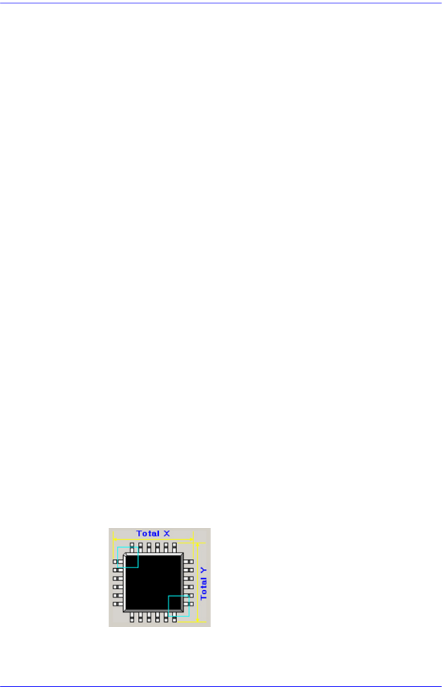
Setup the type of multi-recognition. This function is activated only when ‘Fix1
Cam ~ Fix2 Cam’ is selected in the <Camera No.> combo box.
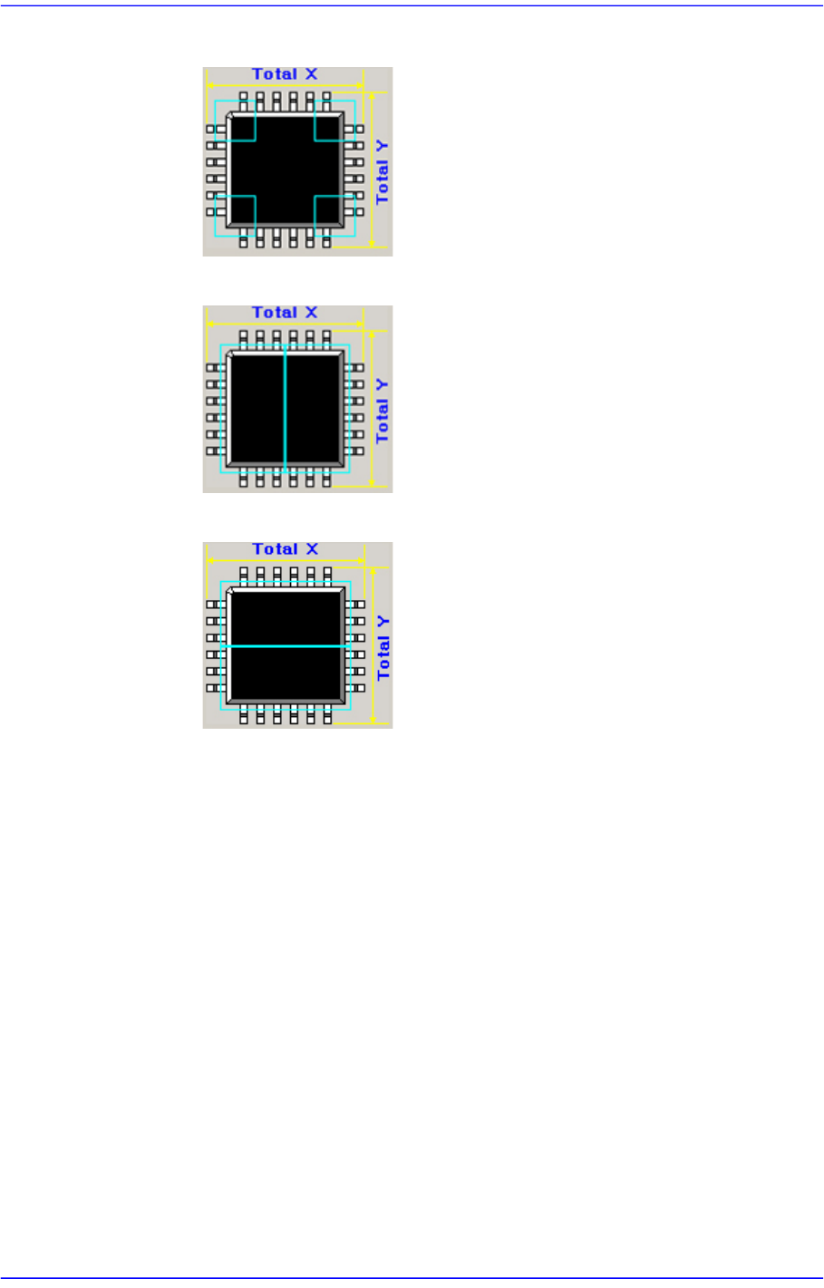
Selectable types are as follows;
None : Does not use multi-recognition type.
Cross 2P : Performs multi-recognition of the two diagonal edges.
7-29
Part Registration
Cross 4P : Performs multi-recognition of four edges.
Linear H : Performs multi-recognition horizontally in two parts.
Linear V : Performs multi-recognition vertically in two parts.
<MFOV Length> edit box
Input the moving distance for multi-recognition.
<EX Param> button
Indicates the dialog box used to set up details related to recognition.
" Extra Parameter " tab screen - IC Lead
Set detail parameters related to the recognition of IC parts such as SOP, SOP2,
SOJ, SOJ2, QFP, PLCC, and UserIC.