DECAN_S2_Admin(Eng_Ver4.5).pdf - 第132页
6-19 Board Definition Figure6.5 “Fi ducial P osition & Mark” dialog box (When the Position Type is “2 Panel”) <No> column A serial number of the posi tion of fiducial mark. <X> column The X position v…
6-18
Advanced Chip Shooter DECAN S2 Administrator’s Guide
That is, it is used if the external machined section of the PCB is very precise or when
there is only one fiducial mark inevitably. Generally, 1 point fiducial is not used.
In the case of 2 fiducial marks, the X, Y and theta of the PCB can be corrected. This is
the most frequently used method.
In the case of 3 fiducial marks, they are used when the deviation of the score value is
great because the surface of the fiducial marks is unstable. If 3 fiducial marks are used,
the machine can calculate the horizontal and longitudinal position more accurately.
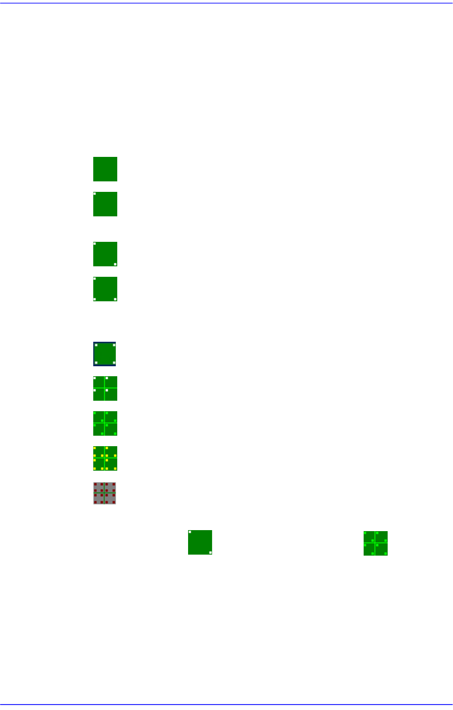
Here, Select the number of fiducial marks. Available numbers are as follows.
None: Fiducial Mark.
1 Panel: In the case of one point, the distortion of the X or Y coordinate can
be compensated.
2 Panel: 2 fiducial marks for PCB correction.
3 Panel: In the case of three points, only two points that obtained higher
points are used selectively when compensating the distortion of the X, Y or R
coordinate of the PCB.
4 Panel: 4 fiducial marks for PCB correction.
1 Array: 1 fiducial mark for Array PCB correction in each Array PCB.
2 Array: 2 fiducial marks for Array PCB correction in each Array PCB.
3 Array: 3 fiducial marks for Array PCB correction in each Array PCB.
4 Array: Each Array PCB has 4 fiducial marks for the calibration of the
PCB board.
It is recommended to use two panels for a general PCB and two arrays for
an array PCB.
<2. Mark Position> group
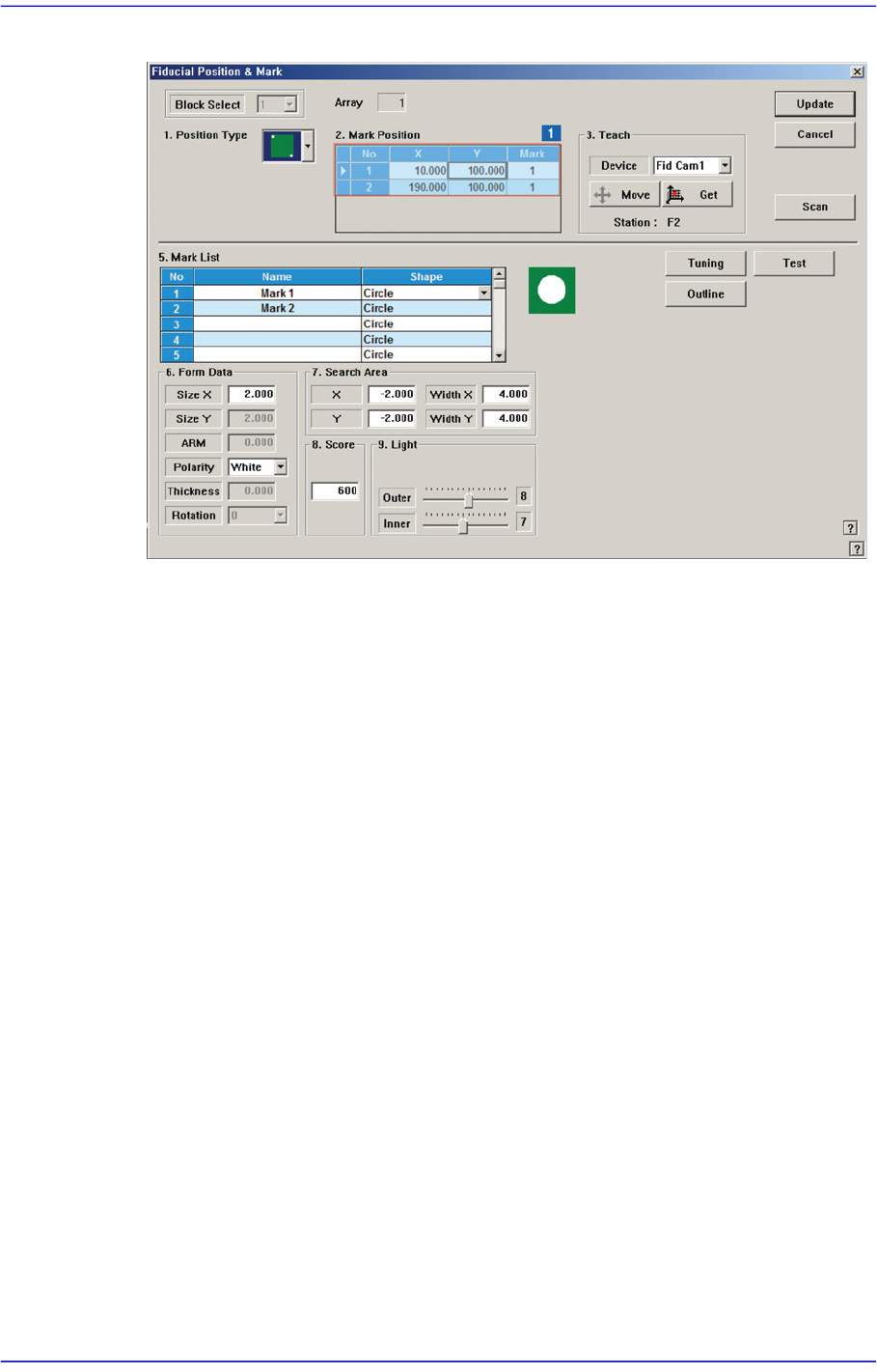
If “None” is not selected in the <1. Position Type> combo box, data is created as many
as the number of the selected fiducial marks. For example, when “2 Panel” is selected,
the following dialog box is displayed.
6-19
Board Definition
Figure6.5 “Fiducial Position & Mark” dialog box (When the Position Type is “2 Panel”)
<No> column
A serial number of the position of fiducial mark.
<X> column
The X position value of fiducial mark.
<Y> column
The Y position value of fiducial mark.
<Mark ID> column
The mark ID value of fiducial mark. This value must be set from a series of
numbers in <5. Mark List>.
<4. Teach > group
Used to teach the fiducial mark position.
<Device> combo box
Select the Camera for checking Fiducial Mark
Fid Cam2: Select the fiducial camera on the front gantry.
Fid Cam4: Select the fiducial camera on the rear gantry.
<Move> button
Move the object selected in the <Device> combo box to the position of the
assigned coordinates. Before executing <Move> button, the cell in the grid
(Coordinates of the fiducial mark) corresponding to the desired position must be
clicked on with a mouse.
6-20
Advanced Chip Shooter DECAN S2 Administrator’s Guide
<Get> button
Obtain coordinates for XY axis with reference to the object selected in the
<Device> combo box. At this time, the objects (Coordinates of the fiducial mark)
related with coordinates must first be clicked with the mouse before clicking on
the <Get> button.
Station
Indicates the station in which the current PCB is to be worked on. (F2: Front, R2:
Rear)
Memo On Fiducial Marks
A fiducial mark has to satisfy several shape and material conditions.
During the design of PCB, the following precautions should be taken.
8 patterns of fiducial mark shapes are possible as shown in the
figure below (top/bottom symmetry or right/left symmetry)
For the size of A, over 2.0㎜ is recommended. The width of mark
sensor beam is about ø0.7㎜ measured from the surface of PCB
Make sure that any changes in color or shape (solder resist, lead
pattern) that can cause error should not be found within 2.0㎜of
fiducial mark's outer edges.
Make sure that the shading difference exits between the fiducial
mark and the board surrounding it.
To ensure search accuracy, coat the surface of the fiducial mark
with copper or lead so that the surface does not reflect. The line
shaped fiducial marks can not be searched with Beam.
<5. Mark List> group
A list of fiducial mark shape data.
<No> column
A serial number of fiducial mark shape.
<Name> column
The name of the fiducial mark. (Up to 10 characters)
<Shape> column
Select the shape of fiducial mark. Available shapes are as follows.
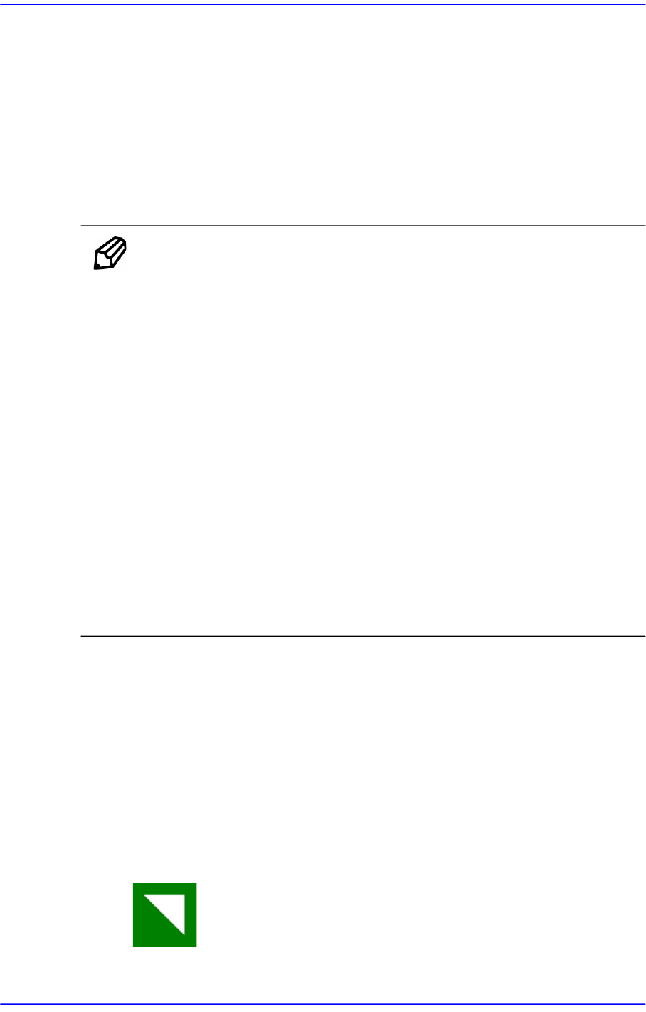
Corner Triangle: Shape of a fiducial mark of a right-angled triangle
shape.