DECAN_S2_Admin(Eng_Ver4.5).pdf - 第99页
4-18 Advanced Chip Shooter DECAN S2 Admi nistra t or’s Guide Head 8/Axis Z When the check box for <From home sensor> i s not ticked, th e height of the nozzle tip of head 8 on the PCB is indi c ated. Head 8/Axi…

4-17
Tools Shortcut Menu
Head 1/Axis Z
When the check box for <From home sensor> is not ticked, the height of the
nozzle tip of head 1 on the PCB is indicated.
Head 1/Axis R
Indicates the presently rotated angle from the home position of R axis for head 1.
Head 2/Axis Z
When the check box for <From home sensor> is not ticked, the height of the
nozzle tip of head 2 on the PCB is indicated.
Head 2/Axis R
Indicates the presently rotated angle from the home position of R axis for head 2.
Head 3/Axis Z
When the check box for <From home sensor> is not ticked, the height of the
nozzle tip of head 3 on the PCB is indicated.
Head 3/Axis R
Indicates the presently rotated angle from the home position of R axis for head 3.
Head 4/Axis Z
When the check box for <From home sensor> is not ticked, the height of the
nozzle tip of head 4 on the PCB is indicated.
Head 4/Axis R
Indicates the presently rotated angle from the home position of R axis for head 4.
Head 5/Axis Z
When the check box for <From home sensor> is not ticked, the height of the
nozzle tip of head 5 on the PCB is indicated.
Head 5/Axis R
Indicates the presently rotated angle from the home position of R axis for head 5.
Head 6/Axis Z
When the check box for <From home sensor> is not ticked, the height of the
nozzle tip of head 6 on the PCB is indicated.
Head 6/Axis R
Indicates the presently rotated angle from the home position of R axis for head 6.
Head 7/Axis Z
When the check box for <From home sensor> is not ticked, the height of the
nozzle tip of head 7 on the PCB is indicated.
Head 7/Axis R
Indicates the presently rotated angle from the home position of R axis for head 7.

4-18
Advanced Chip Shooter DECAN S2 Administrator’s Guide
Head 8/Axis Z
When the check box for <From home sensor> is not ticked, the height of the
nozzle tip of head 8 on the PCB is indicated.
Head 8/Axis R
Indicates the presently rotated angle from the home position of R axis for head 8.
Head 9/Axis Z
When the check box for <From home sensor> is not ticked, the height of the
nozzle tip of head 9 on the PCB is indicated.
Head 9/Axis R
Indicates the presently rotated angle from the home position of R axis for head 9.
Head 10/Axis Z
When the check box for <From home sensor> is not ticked, the height of the
nozzle tip of head 10 on the PCB is indicated.
Head 10/Axis R
Indicates the presently rotated angle from the home position of R axis for head 10.
Mirror
Indicates the presently rotated angle from the home position of mirror rotation axis for
fly camera.
<Close> button
Close the <Position> dialog box, End the <Current Position> command.
4-19
Tools Shortcut Menu
4.7. Manual Tool
Execute this menu for manual operation as follows. This menu should only be executed by
a user with the proper service user authorization.
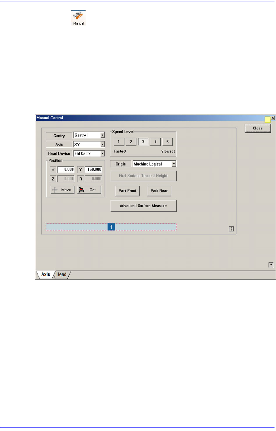
4.7.1. Axis Tab dialog box
Used for moving the selected object by operating the motor for each axis, or for obtaining
the present coordinates of the object.
Figure4.7 “Manual Control – Axis” dialog box
1: Status Indication Area
<Gantry> combo box
Select the gantry to be operated manually.
<Axis> combo box
Select the driving motor to be operated. Selectable driving motors are as follows;
XY: Select the driving motor for X-axis and Y-axis.
Z: Select Z-axis driving motor of the head.
R: Select R-axis driving motor of the head
Mirror: Select the driving motor of mirror for the fly camera.
Conv. Width: Select the motor for adjustment of conveyor width.