DECAN_S2_Admin(Eng_Ver4.5).pdf - 第361页
13-14 Advanced Chip Shooter DECAN S2 Admi nistra t or’s Guide <Shortage W arning Option> combo box Indicates the alar m message box for parts supply error rate when the failure rate of parts supply in t he tray f…
13-13
Production Setup
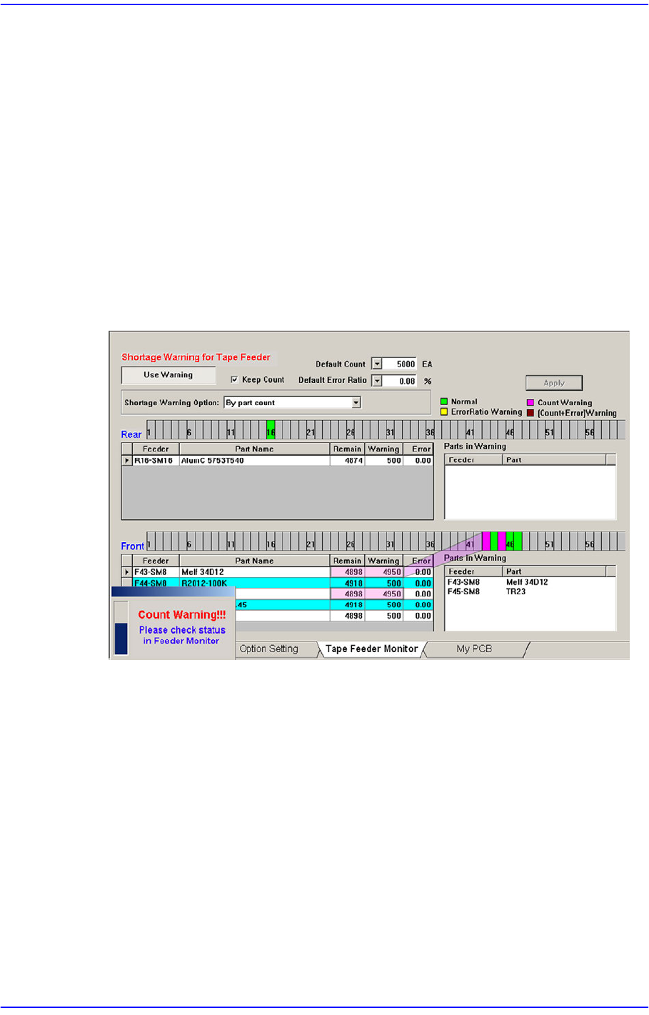
<Use Warning> button
Selects whether to automatically show the alarm message setup in the ‘Tape Feeder
Monitor’ tap dialog box while working. It is setup as ‘use’ in the above dialog box.
<Keep Count> check box
Generally, if the PCB program is downloaded, the remaining quantity is set up to the
default count.
In case the same PCB program must be downloaded again for a particular reason
during operation, select this check box to maintain the Remain Count of the tape
feeder installed already.
<Default Count> combo box
Indicates the part shortage alarm message box when the remaining quantity of parts
supplied to the tape feeder is less than the setup value.
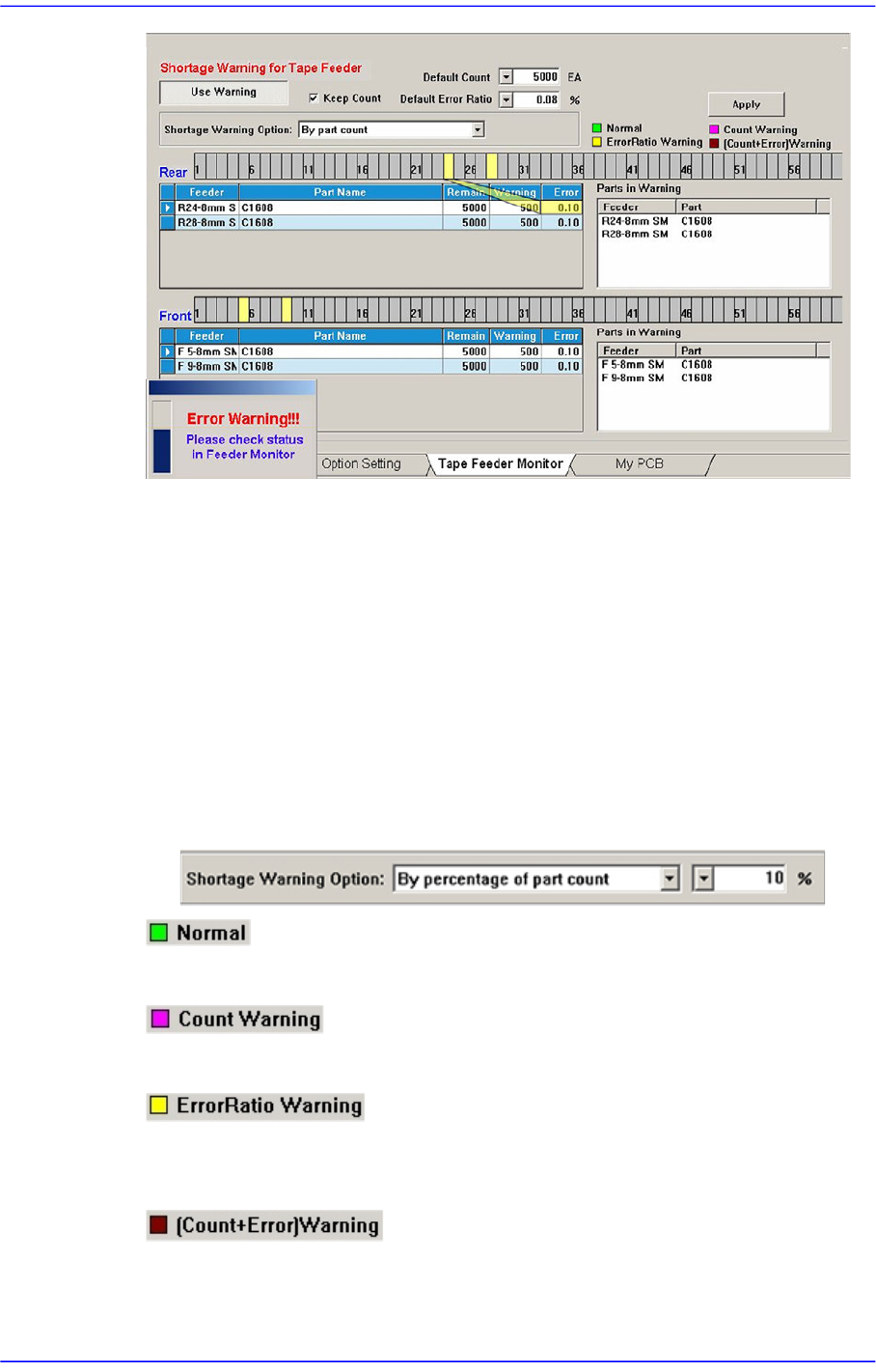
<Default Error Ratio> combo box
Indicates the alarm message box for parts supply error rate when the failure rate of
parts supply in the tray feeder is higher than the setup value.
13-14
Advanced Chip Shooter DECAN S2 Administrator’s Guide
<Shortage Warning Option> combo box
Indicates the alarm message box for parts supply error rate when the failure rate of
parts supply in the tray feeder is higher than the setup value.
By part count
Indicates the warning message based on the part count set in the <Warning>
column.
By percentage of part count
If this is selected, the combo box for selecting percent is created at the right.
Based on the Remain Count, if the part count becomes less than the corresponding
percent, the warning message is indicated.
Indicates normal tape feeder.
Indicates the tape feeder of which the remaining parts are less than the setup value.
Indicates the tape feeder of which the error rates of part supply is higher than the setup
value.
Indicates the tape feeder with simultaneous shortage and defect of remaining parts.
13-15
Production Setup
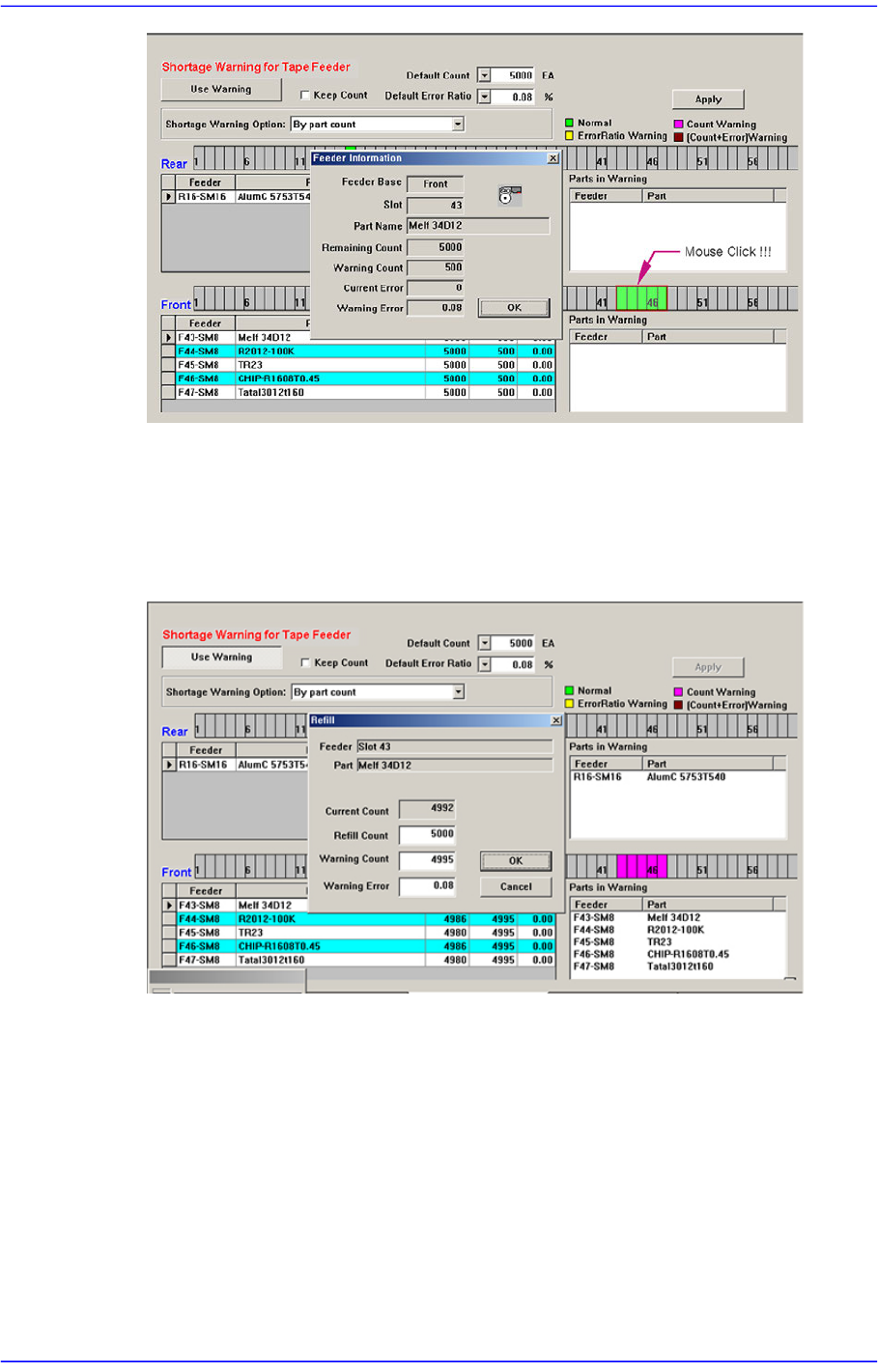
Clicking the mouse on the place at which the feeder is installed will display the
‘Feeder Information’ dialog box as shown above.
However, right clicking the mouse will display the ‘Refill’ dialog box as follows.
When performing the work after splicing reel, change the Remain Count by using the
Refill dialog box.
The values set from the <Default Error Ratio> combo box and <Default Count> in the
Tape Feeder Monitor Tab dialog box are applied.
If the <OK> button is clicked, the value set in the <Refill Count> edit box is added to
the current count to make the Remain Count.
<Apply> button
Generally, if the PCB program is downloaded, the remain count is set up to the default
count.
However, in the case of the part reel to which the Default Count cannot be applied,
select the corresponding tape feeder and set the corresponding count in the <Remain>
column and then click the <Apply> button. Then the change value is applied as the