DECAN_S2_Admin(Eng_Ver4.5).pdf - 第186页
7-21 Part Registration It is recomme nded to use X/Y without setting the of f set. Z For parts f ed by a tape feeder , it i s recommended t o set the Z value ref erring to the follo wing table. <Flux Setting> g…
7-20
Advanced Chip Shooter DECAN S2 Administrator’s Guide
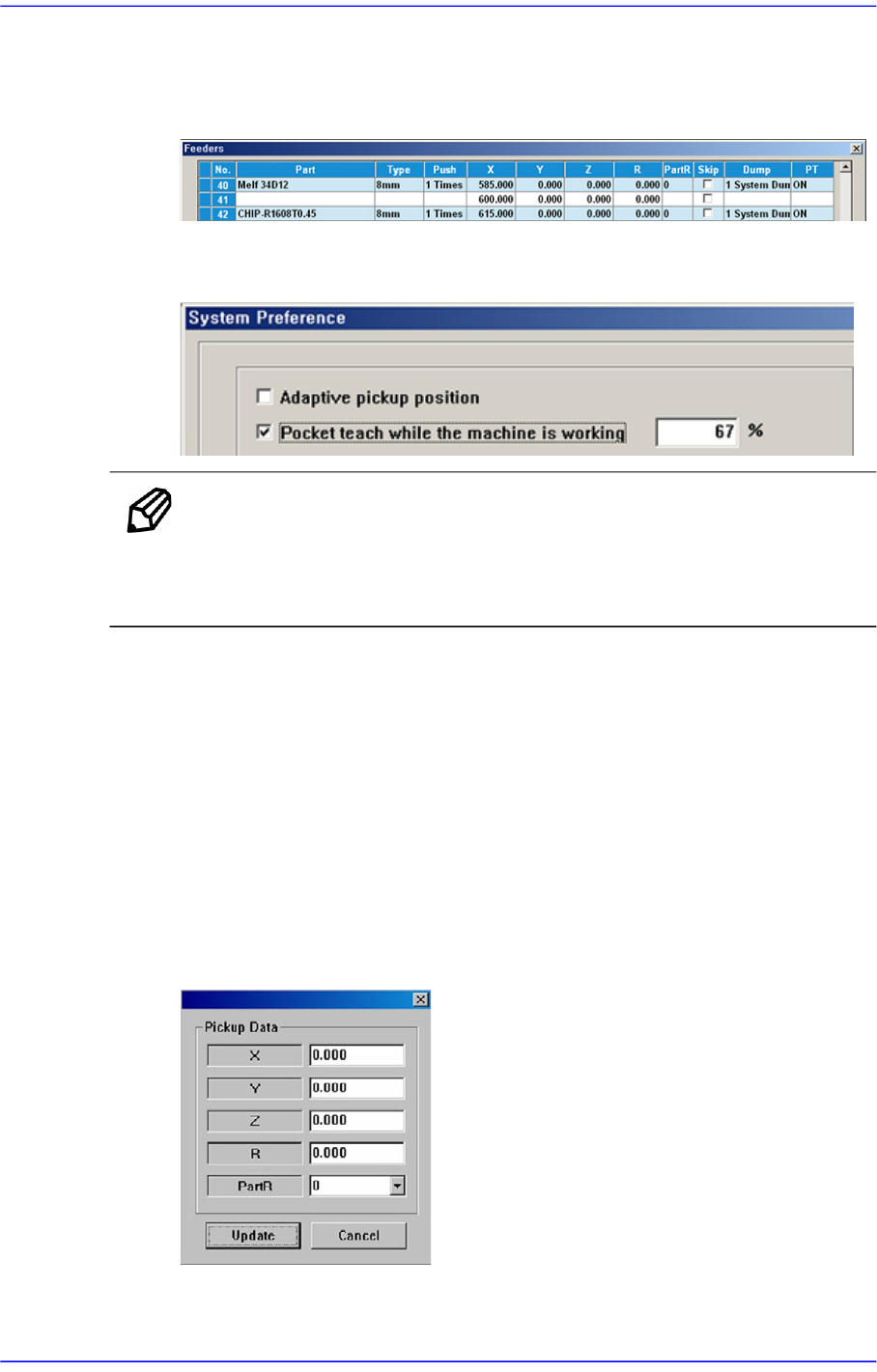
<Enable Pocket Teach> check box
If this check box is selected, the Pocket Teach function of the feeding device that
feeds the corresponding part is automatically set up in the 'Feeders' dialog box.
In order to allow the Pocket Teach to be actually applied, the Pocket Teach option
of the Preference submenu of the System Setup menu must be set up.
Memo For parts fed by an 8mm tape feeder, it is recommended that this
function be applied.
Basically, the black splicing tape must be used.
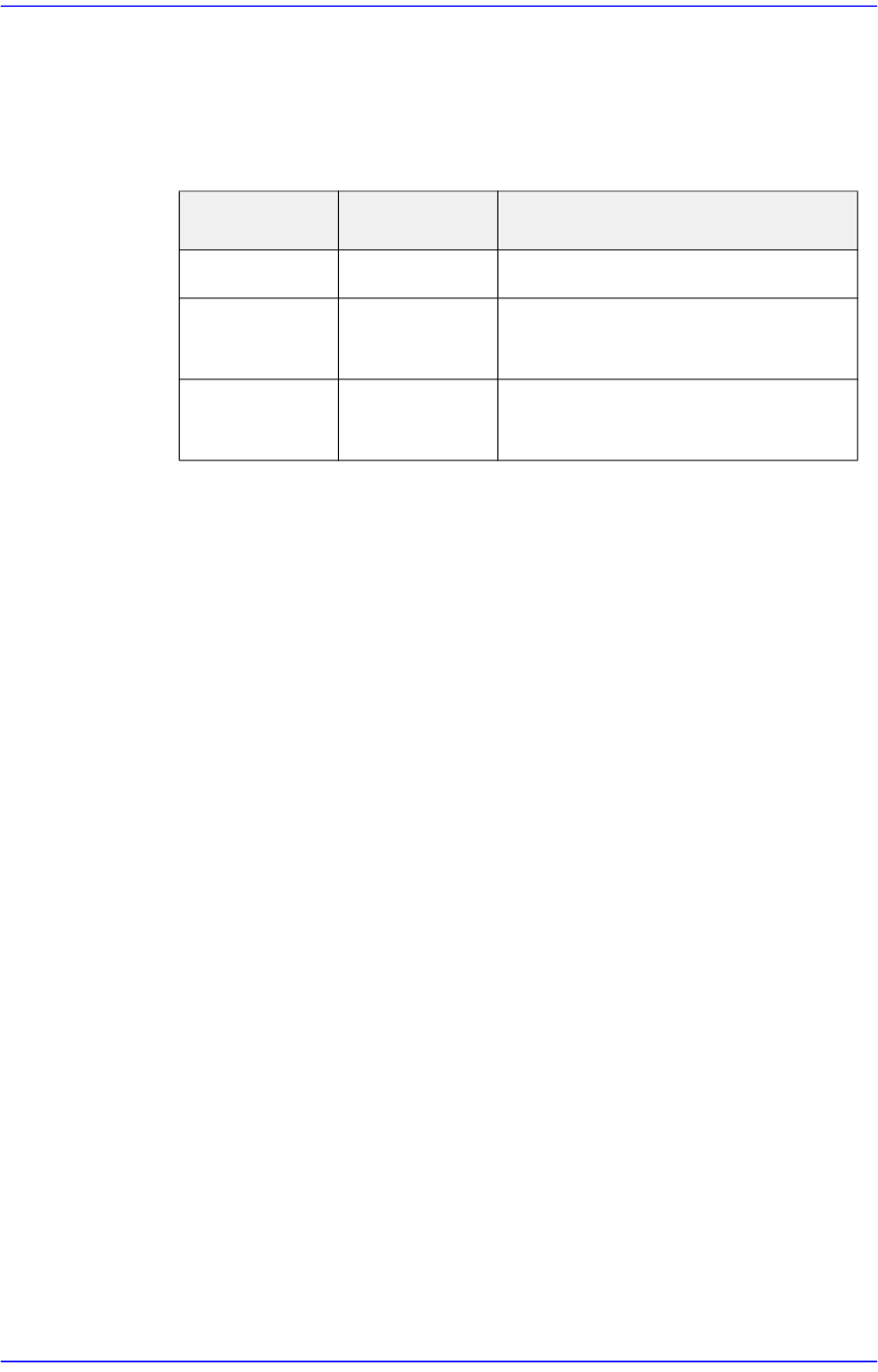
<Pick Up Data> button
Sets the offset of the pickup point coordinate when picking up a specific part. For
some specific parts, the pickup point set by default may differ from the actual
pickup point.
(Example: It is not possible to pick the part at the center)
At this time, after teaching the actual pickup point for the corresponding part, save
the pickup point offset here and register the corresponding part as a part to be
placed and then the offset is automatically applied to the pickup point so that it is
not necessary to teach the pickup point again.
In order to use this function, input the coordinates taught in the edit box.
X/Y
7-21
Part Registration
It is recommended to use X/Y without setting the offset.
Z
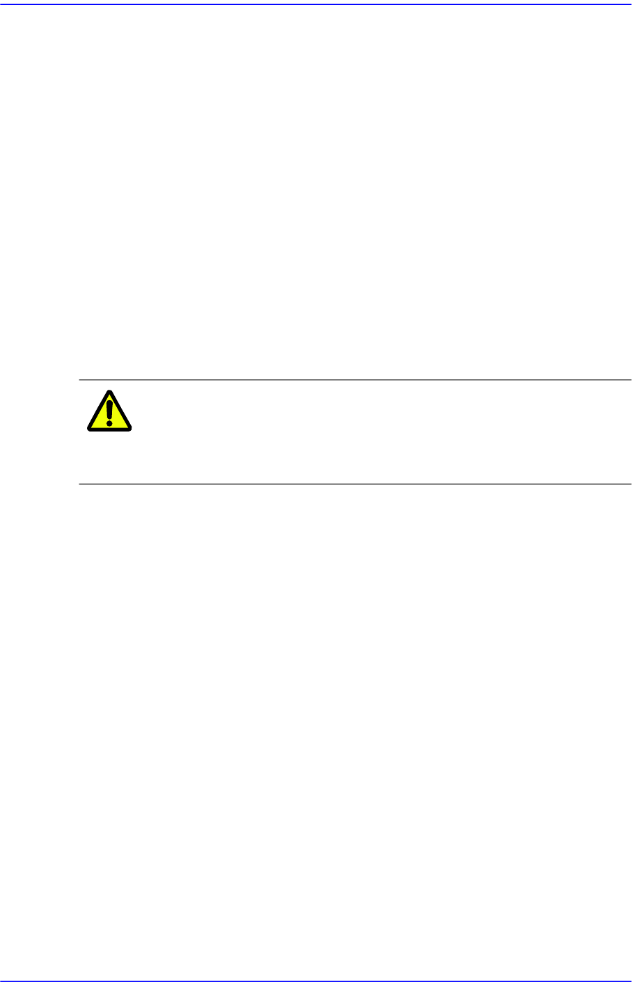
For parts fed by a tape feeder, it is recommended to set the Z value referring to
the following table.
<Flux Setting> group
In the case of flux part, it sets the method for part recognition. This function can
be used for the machine in which a flux device is installed.
<Type> combo box
No Flux
The POP function cannot be used for parts other than the flux part.
Post Flux
Recognizes the part after dipping it in the flux.
Pre Flux
Dips the part in the flux after recognizing it.
<Depth> edit box
Sets the Z axis height to the depth through which the part is dipped in the flux.
Set the depth with “0” as reference according to the characteristic of the part.
<Etc> group
<Dump Angle> combo box
For connectors or large parts such as large ICs, set the dump angle so that they
can be properly dumped into a dump box or tray pallet.
<Mount Method> combo box
Normal
Work on the parts normally
Virtual Pick
If selected, the placement is performed for the corresponding part with
picking up the actual part.
Tape Feeder
Tape Type
Z
8mm Paper PE Part Thickness
8mm Emboss -0.2
(Manual teaching for particular parts)
greater than
12mm
Emboss -0.2
(Manual teaching for particular parts)
7-22
Advanced Chip Shooter DECAN S2 Administrator’s Guide
Part pickup and placement are performed using the center of the part.
However, if the part is long, even though it was placed holding it at the
center, both sides of the long part may contact sufficiently with the PCB.
In this case, this problem can be solved by pressing the part so that both
sides of the part or a certain section of it may contact the PCB.
As such, this function is useful when performing the work by setting the
position corresponding to the section that needs contact on the PCB
without picking up the actual part in order to make the part that was
already placed come into sufficient contact with the PCB.
First, set the placement point by using the specific part that needs such
work, Register the part to which this function is applied and set the
placement point of this part to the position at which the placed part is
pressed. Create as many placement points as needed in this manner.
Then, place the specific part first and make it contact with the PCB using
Virtual Pick.
Caution Using this function may cause serious wear of the nozzle.
We take no responsibility for the occurrence of nozzle wear
due to this function.
<Vacuum Check> check box
Check it to carry out vacuum check during the component pick-up.
Since the micro chip is very small, after it is placed, even though it is not
placed actually, not only is it difficult to detect such error in the post process
but also great effort is needed when placing the part again.
Therefore, if this function is used, the machine remembers the pressure
applied to the part when it was picked up and compares this memorized
pressure to the pressure applied to the part when it is placed finally to check if
there is any variation.
If discrepancy occurs, the part may have been dropped due to a certain reason
while the head moves to the placement point after picking it up.
<Use Compatible Camera> check box
Enables the camera with same FOV as the camera that is designated at the
time of component registration to work for efficient work. For example, in
case the Fix Camera 1 is designated to work, if the FOV is same, it allows the
Fix Camera 2 to work for the work efficiency.
<Barcode> check box
It is possible to enable the feeder list when setting the barcode position. For
more details, refer to “6.6.2. Barcode Position”.