DECAN_S2_Admin(Eng_Ver4.5).pdf - 第446页
14-77 Machine Calibration Memo The reference values for the calibration of the R-Axis Off s et is a s follows. Real Max(Min): The Max.(Min.) offse t between command value and calibration v alue Head1~Head1 0 : -1.0 ~ 1…
14-76
Advanced Chip Shooter DECAN S2 Administrator’s Guide
10. .For Head #2 ~ Head #10, perform calibration in the same manner as it was performed
for Head #1.
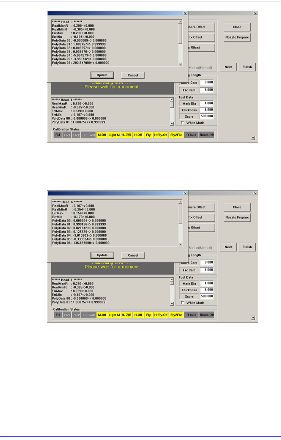
11. .If the calibration procedure is completed for all heads normally, the result is displayed
as shown in the following figure.
12. .Select Gantry 2 in the <Gantry> combo box and perform calibration in the same
manner as has been done for Gantry 1.
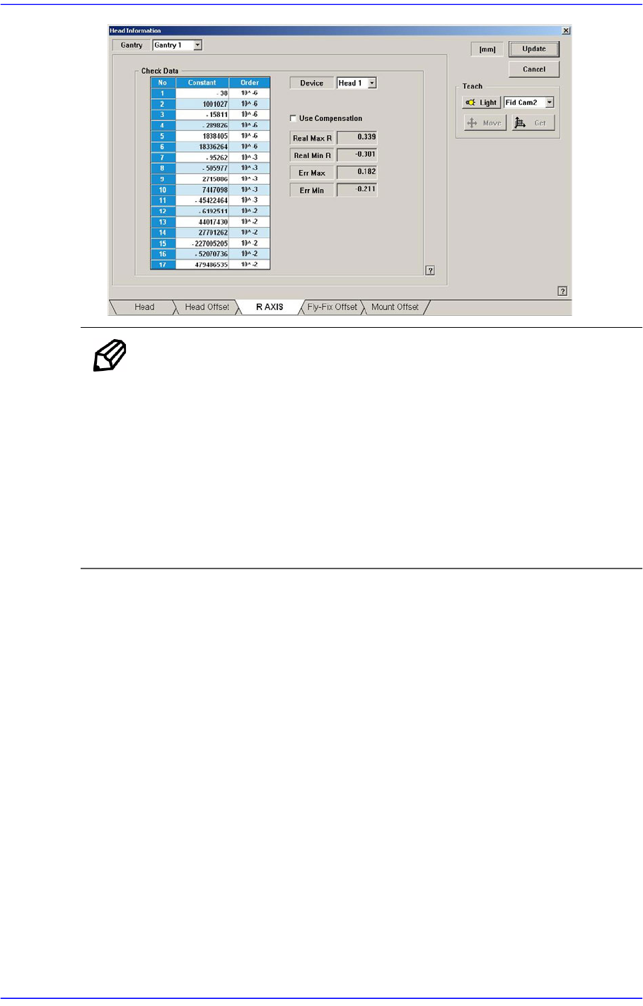
The measurement result can be confirmed in the R Axis dialog box.
14-77
Machine Calibration
Memo The reference values for the calibration of the R-Axis Offset is as
follows.
Real Max(Min): The Max.(Min.) offset between command value
and calibration value
Head1~Head10 : -1.0 ~ 1.0(deg)
Err Max(Min) The Max.(Min.) offset between compensation
value and calibration value
Head1~Head10 : -0.3 ~ 0.3(deg)
14.3.10.9. Beam Offset Calibration
Refers to the calibration measuring the distance between the fiducial camera sensor and
beam sensor. In order to measure the beam offset, the beam sensor to be used in the
<Head> tab of the System menu must be selected first.
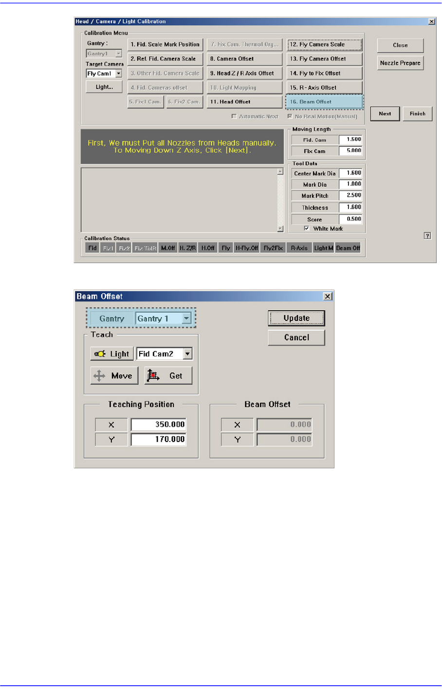
Perform calibration of the Beam Offset in the following manner
1. Press the <16. Beam Offset> button to execute the beam offset dialog box.
14-78
Advanced Chip Shooter DECAN S2 Administrator’s Guide
2. Select the gantry to be calibrated.
3. After selecting the Fid Cam2 (or Fid Cam4) as a teaching camera, move the X-Y axes
to the area (a point that can be distinguished by SMVision) which can be recognized
using the jog box.
4. Press the <Get> button to save the current position in the <Teaching Position>.
5. Select Beam 1 (or Beam 2) as a teaching tool and move it to the <Teaching Position>
using the jog box.
6. Press the <Get> button to save the current position in the <Beam Position>.