DECAN_S2_Admin(Eng_Ver4.5).pdf - 第178页
7-13 Part Registration synchro nized pick up. <Y> edit box Set the allowance in Y d irection as a perc entage of Part Size Y a t the tim e of synchro nized pick up. <Retry> combo box Set the number of ret…
7-12
Advanced Chip Shooter DECAN S2 Administrator’s Guide
<Sync Pick Up Tol[%]> group
As an allowable error for simultaneous pickup, it is indicated in percent based on
the part size.
The default value is 15%. If the set value is greater than this, a pickup error may
be caused even though simultaneous pickup is performed well.
In the case of micro parts, this value must be small, and pocket teaching must be
performed for parts smaller than 1005 part to reduce the part dump rate
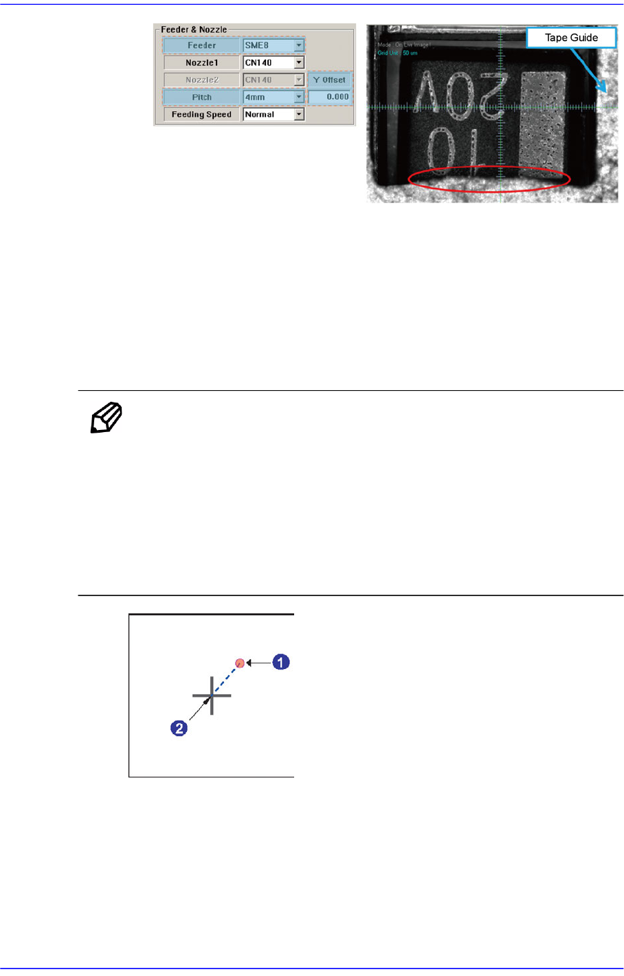
Memo Conditions for Simultaneous Pickup
1. The part must be picked up within the allowable error range of
the center of the head that picks the part.
2. In the case of the interlocked heads, the R value must be identical
when picking up the part.
3. The maximum allowable error of the X and Y must be less than
0.5mm.
Here, the allowable error means the offset from the align point of the part to the
head center, which is the actual pickup point.
1: Head Center (Actual Pickup Point)
2: Part Align Point
<X> edit box
Set the allowance in X direction as a percentage of Part Size X at the time of
7-13
Part Registration
synchronized pick up.
<Y> edit box
Set the allowance in Y direction as a percentage of Part Size Y at the time of
synchronized pick up.
<Retry> combo box
Set the number of retries when the component pickups was not successful.
Available numbers are 1 - 5.
<Delay> group
Set various delay time for pickups, placement, and dump operations. Set the Delay
related to the head movement.
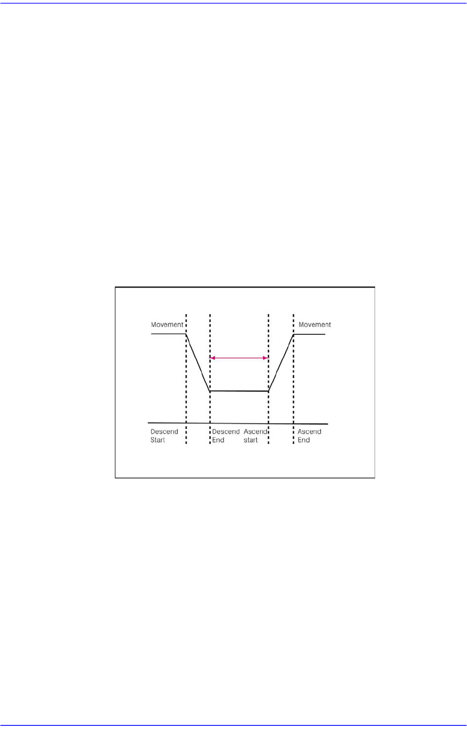
<Pick Up> edit box
During component pickups, the delay time after the head has come down until
the head starts ascending.
Figure7.5 “Pick-Up Delay Time” Delay Time during Placement
<Place> edit box
During component placement, the delay time after the head has come down
until the head starts ascending.
<Blow On> edit box
During component placement, The time from vacuum off till blown on
once the head stops upon completion of descent.
Unit: msec (Possible to setup for 10 msec intervals)
<Dump> edit box
During component dumping, the delay time after the head has come down
until the head starts ascending.
<Vac Off> edit box
During component placement, the delay time after the head has come down
7-14
Advanced Chip Shooter DECAN S2 Administrator’s Guide
until vacuum is off.
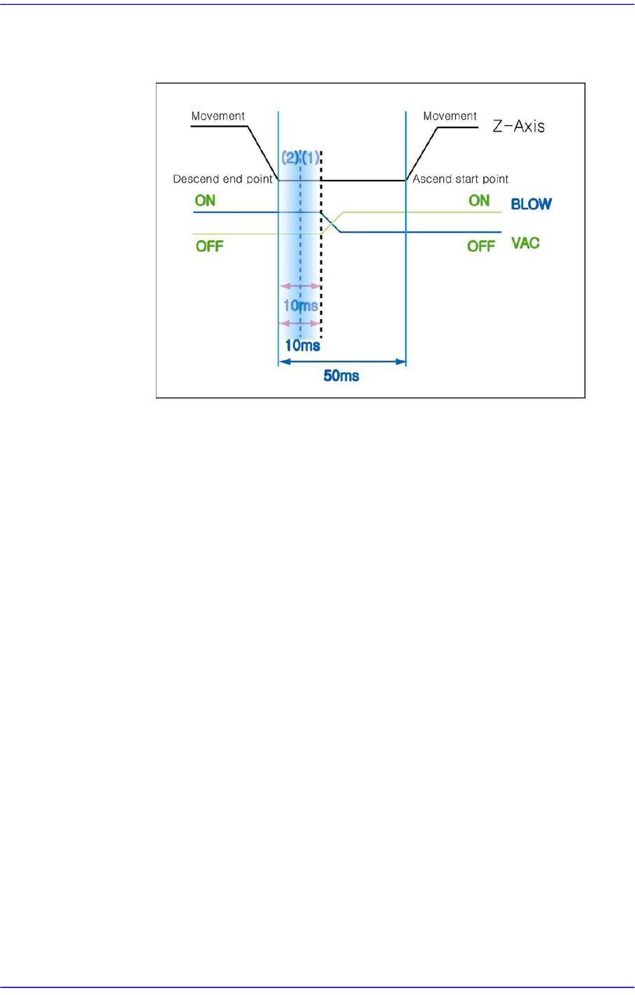
Figure7.6 “Place Delay Time” Delay Time during Placement
For example, if the Place, Vac OFF and Blow ON are set to 50, 10 and 10
respectively:
The time required is 50ms from the time the Z axis finishes moving down
for placement until the Z axis begins to move up after all processes are
completed.
The Vac off 10 means that the vacuum will be turned off in 10ms after the
Z axis finishes moving down for placement.
The Blow ON 10 refers to the delay time from the time the Z axis finishes
moving down to the time the Blow On is performed.
Generally, the Blow ON value is set to the time same as the Vac Off time.