DECAN_S2_Admin(Eng_Ver4.5).pdf - 第205页
7-40 Advanced Chip Shooter DECAN S2 Admi nistra t or’s Guide 7.1.2.2. CHIP-Rect component data setting Set the align data for rectangular CHIP components. Figure7.13 “Pac kage Group =CHIP-R e ct” dialog box <Camer a…
7-39
Part Registration
7.1.2. CHIP component data setting
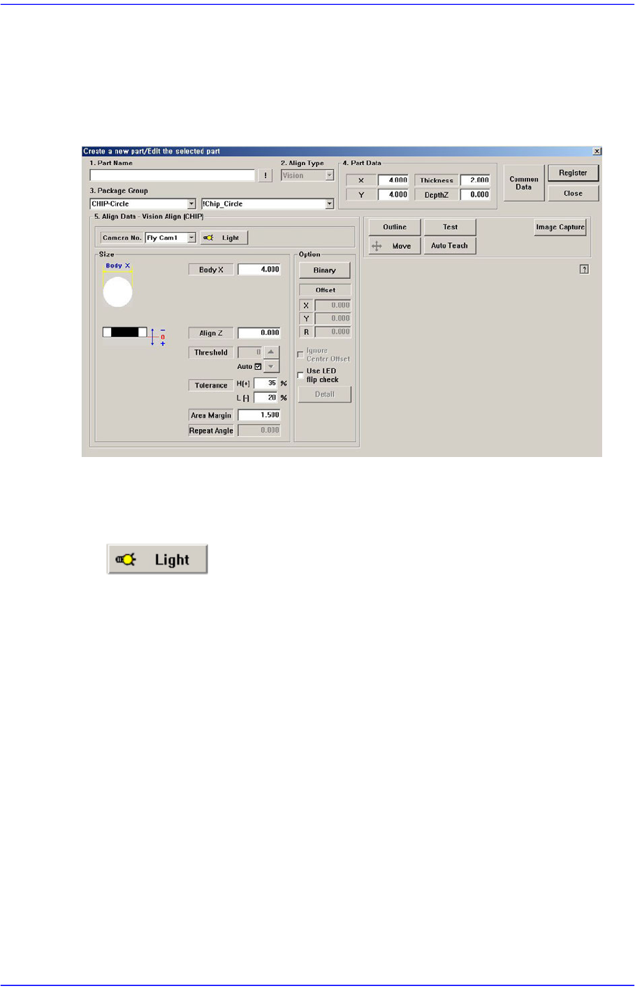
7.1.2.1. CHIP-Circle component data setting
Set the align data for circle CHIP components.
Figure7.12 “Package Group =CHIP-Circle” dialog box
<Camera No.> combo box
Select the camera to recognize the component. Please refer to “7.1.1 Common Align
Data” for more information.
button
Select the light for the camera to recognize the component. Please refer to“7.1.1
Common Align Data” for more information.
<Size> group
Set the align size.
<Body X> edit box
Enter the diameter of the component.
For other setups, please refer to “7.1.1 Common Align Data”.
<Option> group
Set the Option data among Align data related to part recognition.
<Use LED flip check> check box
This is selected to use the function that checks the turnover of the LED. For more
details, refer the “<Detail> Button” of “7.1.2.2CHIP-Rect component data
setting”.
7-40
Advanced Chip Shooter DECAN S2 Administrator’s Guide
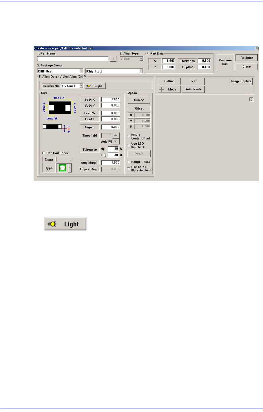
7.1.2.2. CHIP-Rect component data setting
Set the align data for rectangular CHIP components.
Figure7.13 “Package Group =CHIP-Rect” dialog box
<Camera No.> combo box
Select the camera to recognize the component. Please refer to “7.1.1 Common Align
Data” for more information.
button
Select the light for the camera to recognize the component. Please refer to “7.1.1
Common Align Data” for more information.
<Size> group
Set the align size.
<Body X> edit box
Set the component size in X direction.
<Body Y> edit box
Set the component size in Y direction.
<Lead W> edit box
Set the length of lead in X direction.
<Lead L> edit box
Set the length of lead in Y direction.
<Use Coil Check> check box
Used to recognize the coil type parts that could not be recognized properly
7-41
Part Registration
because the part recognition algorithm was unavailable.
<Score> edit box
Enabled when the <Use Coil Check> is selected.
"Score” is the numerical value that indicates how accurately the recognized
part shape matches with the vision algorithm data selected from the <Type>
combo box when recognizing the part shape. This "Score” has a value
between 0 and 1000 points.
Here, even if ‘0’ is entered, 300 is applied as a default value.
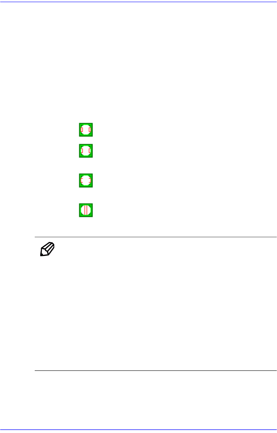
<Type> combo box
Select the coil part to be recognized, which has adequate shape.
: When the bright shapes on the right and left are recognized clearly.
: When the outer frames of bright shapes on the right and left are
unclear.
: When the inner frames of bright shapes on the right and left are
unclear.
: When the central shape of the part is recognized clearly.
For other setups, please refer to“7.1.1 Common Align Data”.
Memo Align Data Setup for 0603 Part
Since the 0603R has small difference between the images when
the part is picked up normally and abnormally, the L in the
Tolerance Item must be set to 10%.
In the case of the 0603C, since its size looks slightly different
according to the lighting condition, the L in the Tolerance Item
must be set to 20%.
Set the 0603L identical to the 0603C.
At this time, set the side lighting to 6 and outer lighting to 5.
It is recommended to register a part using the ‘Automatic
Recognition’ function.
<Option> group
Set the align option data.