DECAN_S2_Admin(Eng_Ver4.5).pdf - 第429页
14-60 Advanced Chip Shooter DECAN S2 Ad ministra tor’s Guid e Memo The range of the referenc e value for the ‘head of f s et calibration’ are as follows: Head 1 X:-0.06mm~0.06m m , Y : -0.05mm~0.05m m Head 2 X:14.9 4…
14-59
Machine Calibration
11. .Select Gantry 2 in the <Gantry> combo box and perform calibration in the same
manner as has been done for Gantry 1.
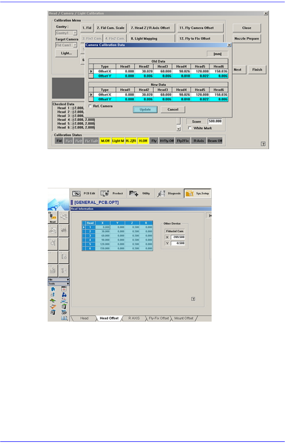
The measurement result can be confirmed in the Head Offset dialog box.
14-60
Advanced Chip Shooter DECAN S2 Administrator’s Guide
Memo The range of the reference value for the ‘head offset calibration’ are
as follows:
Head 1
X:-0.06mm~0.06mm, Y: -0.05mm~0.05mm
Head 2
X:14.94mm~15.06mm, Y: -0.05mm~0.05mm
Head 3
X:29.94mm~30.06mm, Y: -0.05mm~0.05mm
Head 4
X:44.94mm~45.06mm, Y: -0.05mm~0.05mm
Head 5
X:59.94mm~60.06mm, Y: -0.05mm~0.05mm
Head 6
X:74.94mm~75.06mm, Y: -0.05mm~0.05mm
Head 7
X:89.94mm~90.06mm, Y: -0.05mm~0.05mm
Head 8
X:104.94mm~105.06mm, Y: -0.05mm~0.05mm
Head 9
X:119.94mm~120.06mm, Y: -0.05mm~0.05mm
Head 10
X:134.94mm~135.06mm, Y: -0.05mm~0.05mm

14-61
Machine Calibration
Head 11
X:-0.06mm~0.06mm, Y: -0.05mm~0.05mm
Head 12
X:-15.06mm~-14.94mm, Y: -0.05mm~0.05mm
Head 13
X:-30.06mm~-29.94mm, Y: -0.05mm~0.05mm
Head 14
X:-45.06mm~-44.94mm, Y: -0.05mm~0.05mm
Head 15
X:-60.06mm~-59.94mm, Y: -0.05mm~0.05mm
Head 16
X:-75.06mm~-74.94mm, Y: -0.05mm~0.05mm
Head 17
X:-90.06mm~-89.94mm, Y: -0.05mm~0.05mm
Head 18
X:-105.06mm~-104.94mm, Y: -0.05mm~0.05mm
Head 19
X:-120.06mm~-119.94mm, Y: -0.05mm~0.05mm
Head 20
X:-135.06mm~-134.94mm, Y: -0.05mm~0.05mm
14.3.10.5. Fly Camera Scale Calibration
This calibration is performed to find the scale and rotation offset of the fly-camera. In
order to calibrate the scale and rotation of the fly-camera, the ‘fix-camera calibration’ and
‘head Z-offset calibration’ must be performed in advance and the CN400 Nozzle must be
used.
The following is the procedure to calibrate the ‘Fly-Camera Scale Calibration’
1. Click the <Nozzle Prepare> button and insert the CN400 nozzle into the No. 1 hole of
the ANC manually.
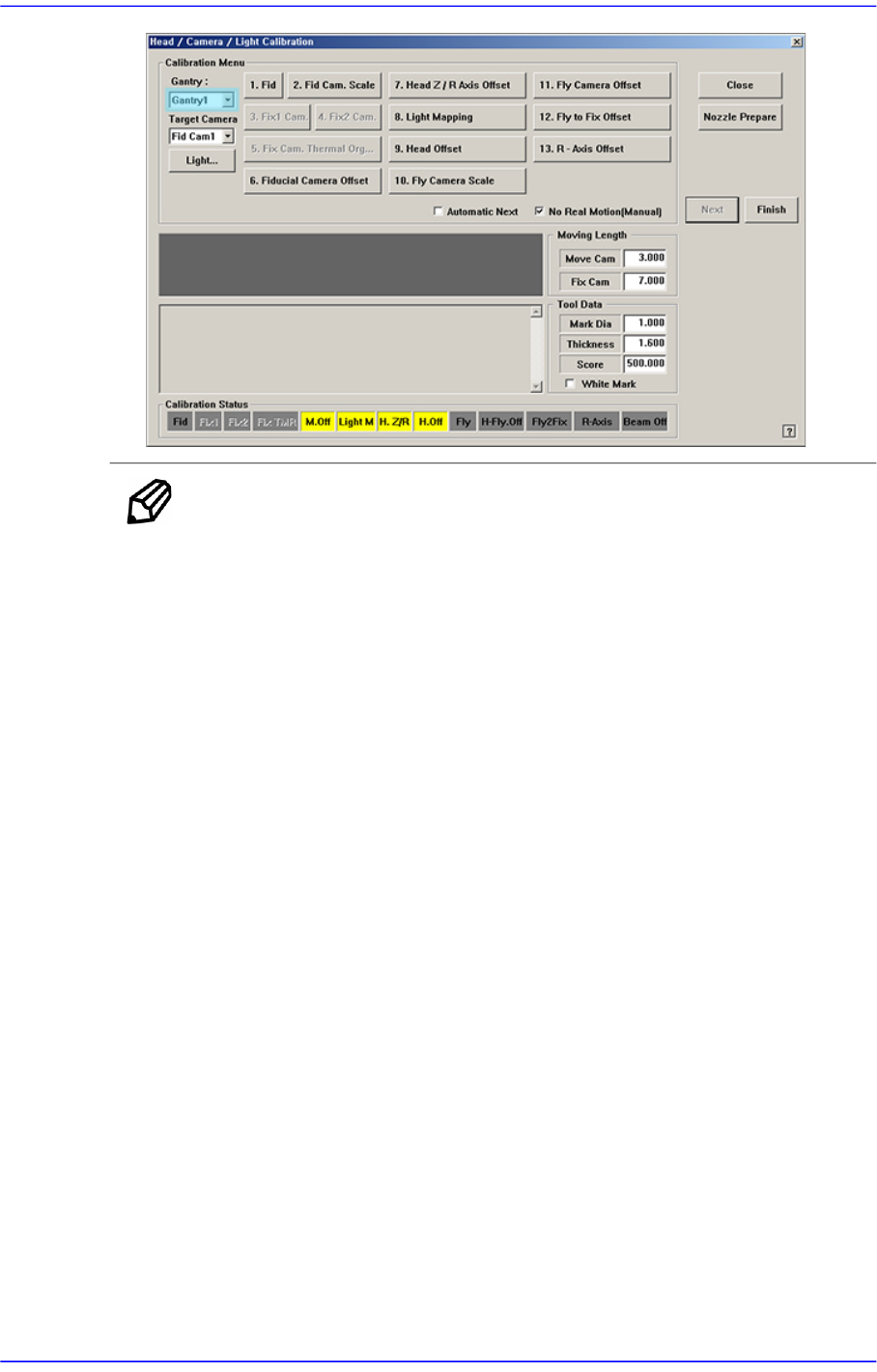
If the <10 Fly Camera Scale> is clicked after selecting the <Automatic Next> check
box, calibration is performed for the selected gantry automatically.
If calibration is performed after selecting the <No Real Motion [Manual]> check box,
the nozzle is inserted into each head manually. Click the <Next> button to move onto
the next step.