DECAN_S2_Admin(Eng_Ver4.5).pdf - 第358页
13-11 Production Setu p <Z A x i s Mount Delay> slide bar W orks after adding the defined value in the slider ba r to the placement delay value setup in t he common data at the time o f part registr ation. This v…
13-10
Advanced Chip Shooter DECAN S2 Administrator’s Guide
Caution This function allows the placement to be simply performed
continuously. If interference is expected in the future
between the skipped part and the nearby placed parts while
performing placement, release this function.
<FIFO Board Processing(Join Only)> check box
If the part placement on the PCB which was performed first on the dual lane
conveyor is not completed, do not perform placement on the PCB on the other
lane. This may be used to improve the balancing in the line. However, the line
productivity owing to this may actually vary depending on the operation condition
<Bad Mark Transferring> check box
This function is used when a scanner made by D-TEK is used. For more details
regarding this, contact us.
<Self Board Fiducials> check box
When the machine operation mode is 'Join', select this check box in order to
increase the part placement accuracy by having the front and rear gantries
recognize the fiducial marks on the PCB respectively.
<Soft Ground> check box
When the machine is installed at a location of soft ground, selecting this check box
will reduce the vibration and noise that occurs due to instantaneous acceleration of
the XY axes.
<PCB Transfer Speed> combo box
Used to adjust the PCB feeding speed. When the PCB is heavy, if it is selected at too
high speed, the conveyor belt may not feed the PCB sufficiently with the belt rotating
while slipping. The default selection is Middle. Adjust the speed appropriately, if
necessary.
Fast: high speed
Middle: medium
Slow: low speed
<Speed> slide bar
Select the driving speed of the XY axis driving motor.
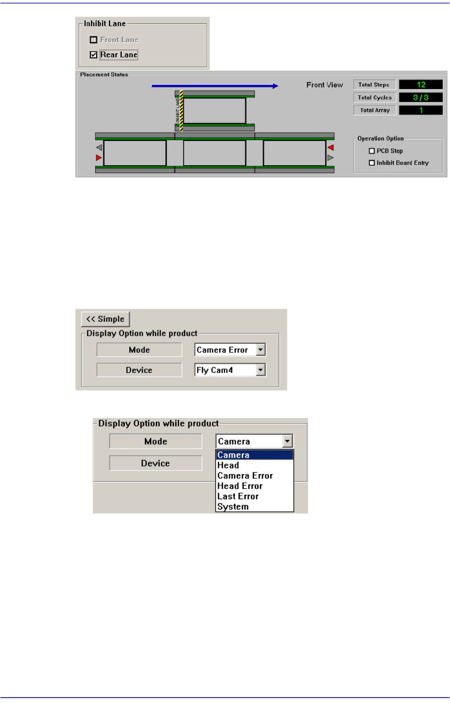
<Inhibit Lane> group
When it is not used, select the workstation. Then the PCB is not loaded on the
corresponding workstation.
13-11
Production Setup
<Z Axis Mount Delay> slide bar
Works after adding the defined value in the slider bar to the placement delay value
setup in the common data at the time of part registration. This value is applied only to
Z-axis.
<Detail> button
This button is used to select the image viewed in the SMVision window during PCB
production.
<Mode> combo box
Camera
Selected when looking at the image of a specific camera. Select the
corresponding camera from the <Device> combo box.
Head
Selected when looking at the image in which the part picked up by a specific
head is recognized. Select the corresponding head from the <Device> combo
box.
Camera Error
Selected when looking at the image of part recognition error from a specific
13-12
Advanced Chip Shooter DECAN S2 Administrator’s Guide
camera.
It shows the recognized part image according to the placement order during
placement. However, if the placement is completed, the camera selected in the
following <Device> combo box shows the part image error that occurred last.
Head Error
Selected when looking at the recognition error image of part picked up by a
specific head.
It shows the recognized part image according to the placement order during
placement. However, if the placement is completed, it shows the image of part
recognition error that occurred last among the parts placed by the head
selected in the following <Device> combo box.
Last Error
It shows the recognized part image according to the placement order during
placement. However, if the placement is completed, it shows the image of part
recognition error that occurred last during placement.
System
Shows the part recognition image according to the placement order.
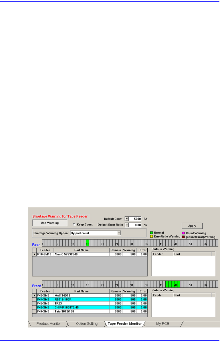
13.1.3. Tape Feeder Monitor
Sets the quantity of remaining components. It shows the remaining components of the
installed tape feeder and alarms against the component shortage. Able to monitor the
errors related with parts supply of tape feeder.
Figure13.5 “Tape Feeder Monitor” tab dialog