DECAN_S2_Admin(Eng_Ver4.5).pdf - 第198页
7-33 Part Registration <Direction Check> tab sc reen Applied to IC parts and ball parts in the same manner . <Body Polarity> combo box Set the polarity of the body whose d i rection is to be checked. Don’…
7-32
Advanced Chip Shooter DECAN S2 Administrator’s Guide
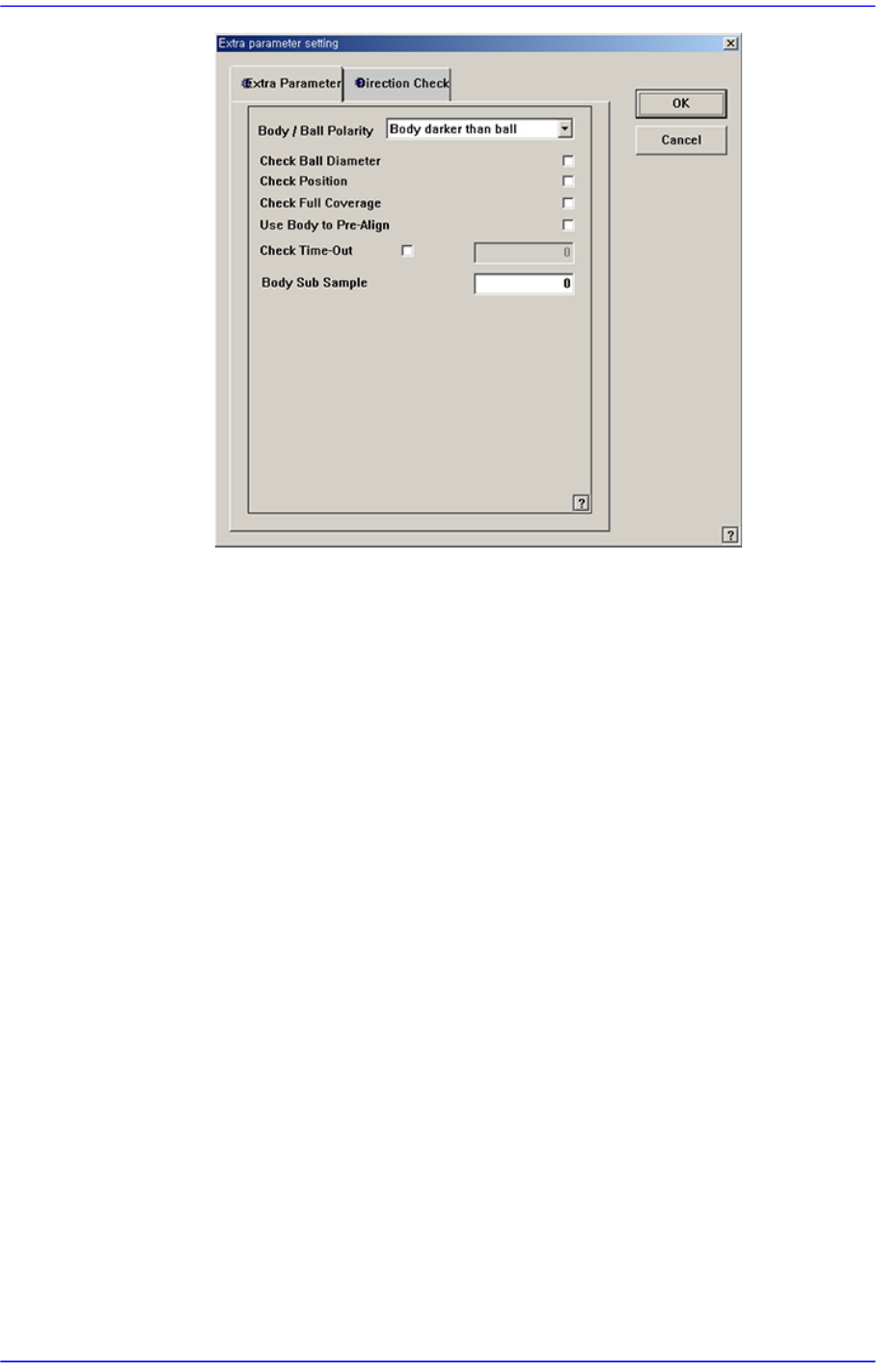
<Body/Ball Polarity> combo box
Set the brightness between the body and the ball.
- Body darker than ball : The body is darker than the bal.
- Body lighter than ball : The body is darker than or no less dark than the
ball.
<Check Ball Diameter> check box
Checks the position of each ball to see if it is within the allowable value.
<Check Position> check box
Checks the position of each ball to see if it is within the allowable value..
<Check Full Coverage> check box
If this option is checked, all balls must be checked. Only when all balls are
within the allowable error, the recognition is successfully performed. If
this option is not checked, even though recognition failure occurs for
some balls, the part center is calculated by using the remaining balls.
<Use Body to Pre-Align> check box
Calculate the approximate position of the part by using the part body
information when recognizing the part.
<Check Time-Out> check box
Set the recognition time out when recognizing the part (unit: msec)
<Body Sub Sample> check box
Set the degree of the sampling when recognizing the part. (0~10, 0: auto)
7-33
Part Registration
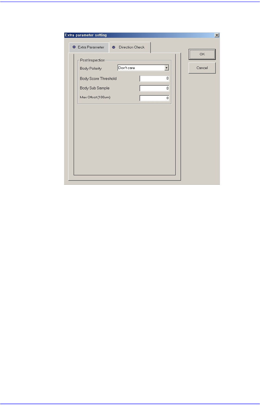
<Direction Check> tab screen
Applied to IC parts and ball parts in the same manner.
<Body Polarity> combo box
Set the polarity of the body whose direction is to be checked.
Don’t care: Selected when recognizing the body whose direction is to be
checked regardless of the polarity.
Dark On Light: Selected when the body whose direction is to be checked
is darker than the background.
Light On Dark: Selected when the body whose direction is to be checked
is brighter than the background.
<Body Score Threshold> edit box
Set the threshold of the body whose direction is to be checked. (0~100).
<Body Sub Sample> edit box
Set the degree of sampling of the body whose direction is to be checked.
(0~10, 0: auto).
<Max Offset[100um]> edit box
Set the maximum allowable error of the body whose direction is to be
checked. (0~10).
<Outline> button
Shows the image seen through the Vision in real display to which threshold is not
applied, or in the image (Binary) to which threshold is applied as recognized by MMI.
7-34
Advanced Chip Shooter DECAN S2 Administrator’s Guide
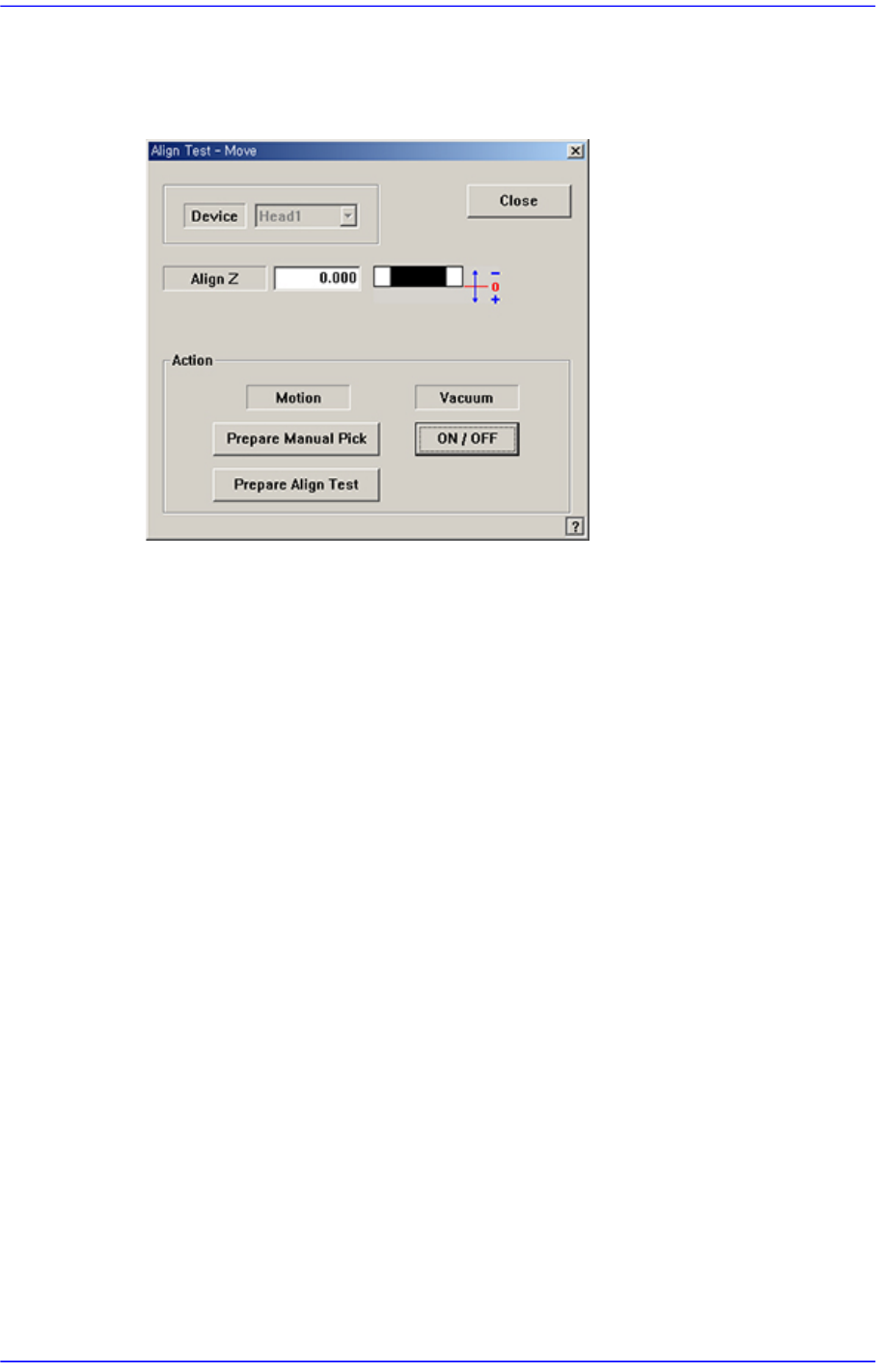
<Move> button
Used for parts recognition test by manually picking up parts. When this button is
clicked on, the following dialog box is displayed.
<Device> combo box
Select the camera to be used for parts recognition.
Only when “Fix Cam1” is selected from the <Camera No.> combo box in the Edit
Part dialog box will the “Align Test” be executed.
<Align Z> edit box
Set the height for recognition. Based on the component surface, if the top is to be
recognized, set - value, and if the bottom is to be recognized, set +value.
<Action> group
<Prepare Manual Pick> button
Moves the head block to the pick-up position when the component is to be
picked to the head manually. Moves to the Home position of the equipment.
<Prepare Align Test> button
When the camera recognizing parts is “Fly Camera”, move the height of the
Z-axis at the tip of the nozzle installed at the head to the align height, close
mirror, and illuminate the part.
When the camera recognizing the parts is “Fix Camera”, move the height of
the Z-axis at the tip of the nozzle installed at the head to a safe height, move
the head assembly to the position of fix camera, and move the Z-axis height at
the tip of the nozzle to the part recognition height (align height).
<Vacuum ON/OFF> button
Turns on/off the vacuum generator of the head for the component pick-up or
release.