DECAN_S2_Admin(Eng_Ver4.5).pdf - 第235页
7-70 Advanced Chip Shooter DECAN S2 Admi nistra t or’s Guide <Length Max> column Input the maximum allowable lea d length. Input value = Lead Length + Allowable Error <Length Min> column Input the minimum…
7-69
Part Registration
7.1.4.1. Lead Parameter
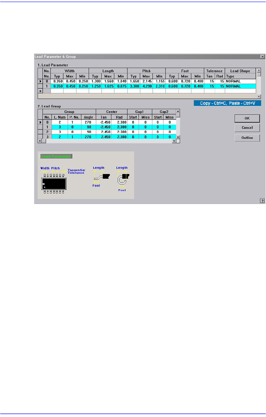
Sets the lead Parameter and lead group of the lead component.
Figure7.25 Screen showing “Lead Parameter” setting in the dialog box for “User IC Lead
Parameter & Group “
<Lead Parameter> group
Set the lead parameter.
<No.> column
Displays the lead parameter number. Possible range is 0 –7.
<Width Type> column
Set the lead width.
<Width Max> column
Input the maximum allowable lead width. (Input value = Lead Width + Allowable
Error). That is, even though the recognized lead is a maximum of 1.2mm when the
actual lead width is 1mm, if this recognized value is allowed, the maximum
allowable lead width will be 1.2mm
<Width Min> column
Input the minimum allowable lead width. (Input value = Lead Width - Allowable
Error). That is, even though the recognized lead is a maximum of 0.8mm when the
actual lead width is 1mm, if this recognized value is allowed, the maximum
allowable lead width will be 0.8mm
<Length Type> column
Set the lead length.

7-70
Advanced Chip Shooter DECAN S2 Administrator’s Guide
<Length Max> column
Input the maximum allowable lead length.
Input value = Lead Length + Allowable Error
<Length Min> column
Input the minimum allowable lead length.
Input value = Lead Length - Allowable Error
<Pitch Type> column
Set the lead pitch, which is the length from the center of the lead to the center of
the adjacent lead. Since this parameter is sensitive to part recognition, draw the
outline of the part in the SMVision window when registering a part and input the
pitch so that the shape of an actual part matches the outline of the part.
<Pitch Max> column
Input the maximum allowable lead pitch
Input value = Lead Pitch - Allowable Error
<Pitch Min> column
Input the minimum allowable lead pitch.
Input value = Lead Pitch + Allowable Error
<Foot Type> column
Set the length of the lead that touches the surface.
<Foot Max> column
Input the maximum allowable foot length.
Input value = Foot Length + Allowable Error
<Foot Min> column
Input the minimum allowable foot length.
Input value = Foot Length - Allowable Error
<Tolerance Tan> column
Set the allowable tolerance when the lead is bent to the side. Set it as a percentage
of <Lead Pitch>
<Tolerance Rad> column
Set the allowable tolerance for lead length. Set it as a percentage of <Lead
Length>.
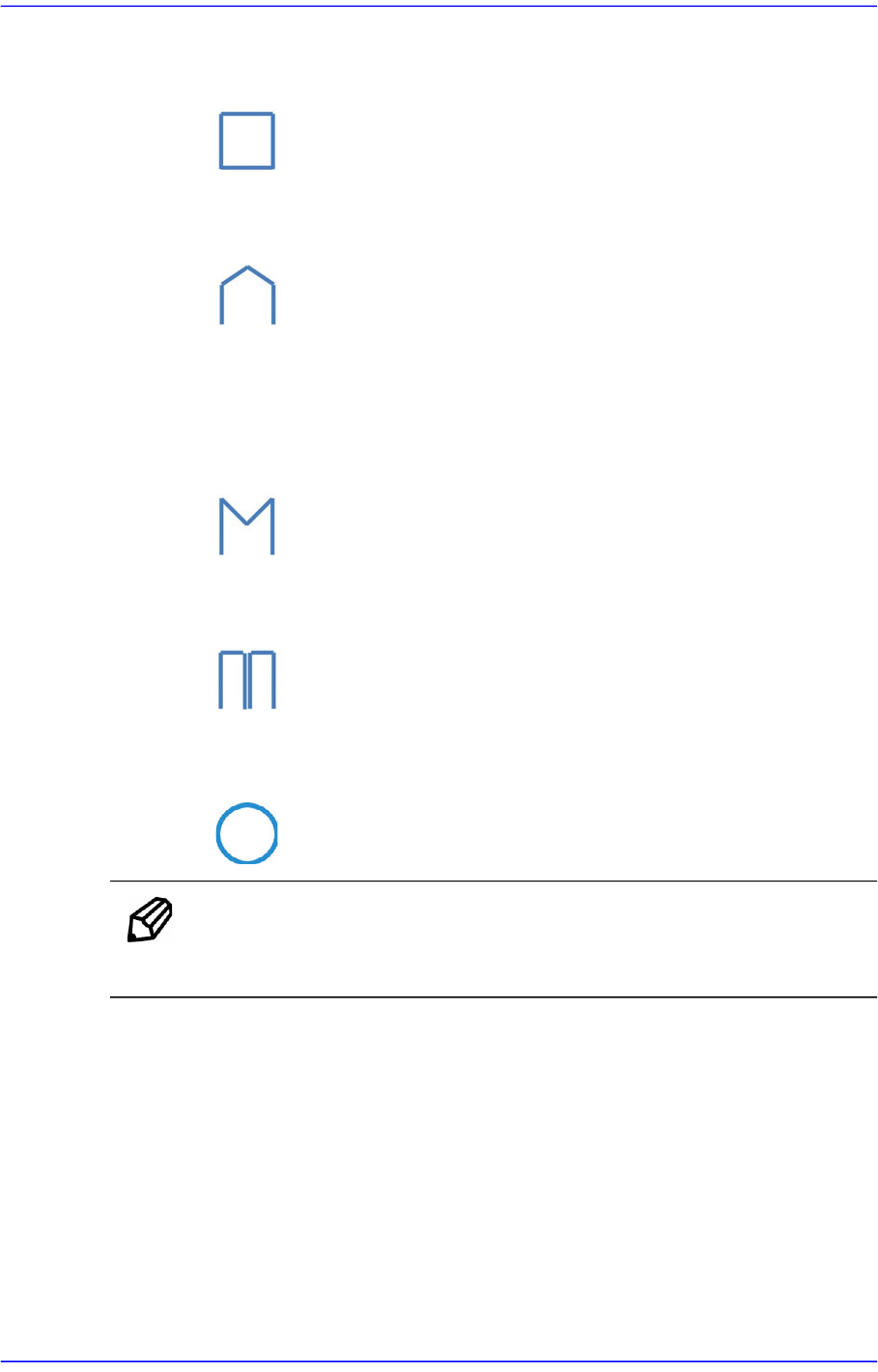
<Lead Shape> column
Select the lead shape.
<NORMAL>
Selected when recognizing the general lead shape.
7-71
Part Registration
<LAND>
Selected when recognizing the lead shapes as follows.
<ROOF>
Selected when recognizing the lead shapes as follows.
<INSERT>
Selected when recognizing the lead shape of the Insert part.
<FORK>
Selected when recognizing the lead shapes as follows.
<TWIN>
Selected when recognizing the lead shapes as follows.
<CIRCLE>
Selected when recognizing the lead shapes as follows.
Memo Set the lead group so that the pitch between the lead groups is greater
than the pitch between leads.