DECAN_S2_Admin(Eng_Ver4.5).pdf - 第377页
14-8 Advanced Chip Shooter DECAN S2 Ad ministra tor’s Guid e T ransmits the change data to the equipment and closes the dialog box. <Cancel> button Ignores the change data and closes the dialog bo x . 14.1.5. <…
14-7
Machine Calibration
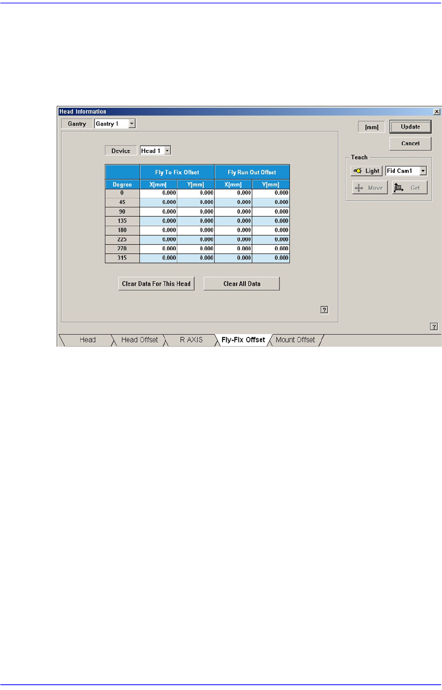
14.1.4. <Fly-Fix Offset> tab dialog
Sets the Fly-Fix offset for each head. Data in this dialog box is updated automatically if the
Fly to Fix Offset Calibration is executed during camera calibration and the result value is
reflected.
Figure14.4 “Fly-Fix Offset” tab dialog
<Device> combo box
Sets the Fly-Fix offset for each head.
<Fly To Fix Offset>
<Degree> column
Sets the Fly-Fix offset by degree at 45 degree interval.
<X, Y> column
Sets the Fly-Fix offset of X, Y.
<Fly Run Out Offset>
<Degree> column
Fly-Fix offset for each angle can be setup at the interval of 45 degrees.
<X, Y> column
Sets the Fly Run Out offset of X, Y.
<Clear data for this Head> button
Deletes Fly-Fix offset data of the selected head. Used when not applying the Fly-Fix
offset on the head. Data cannot be restored once it has been deleted. To apply the Fly-
Fix offset, the camera calibration must be performed again.
<Update> button
14-8
Advanced Chip Shooter DECAN S2 Administrator’s Guide
Transmits the change data to the equipment and closes the dialog box.
<Cancel> button
Ignores the change data and closes the dialog box.
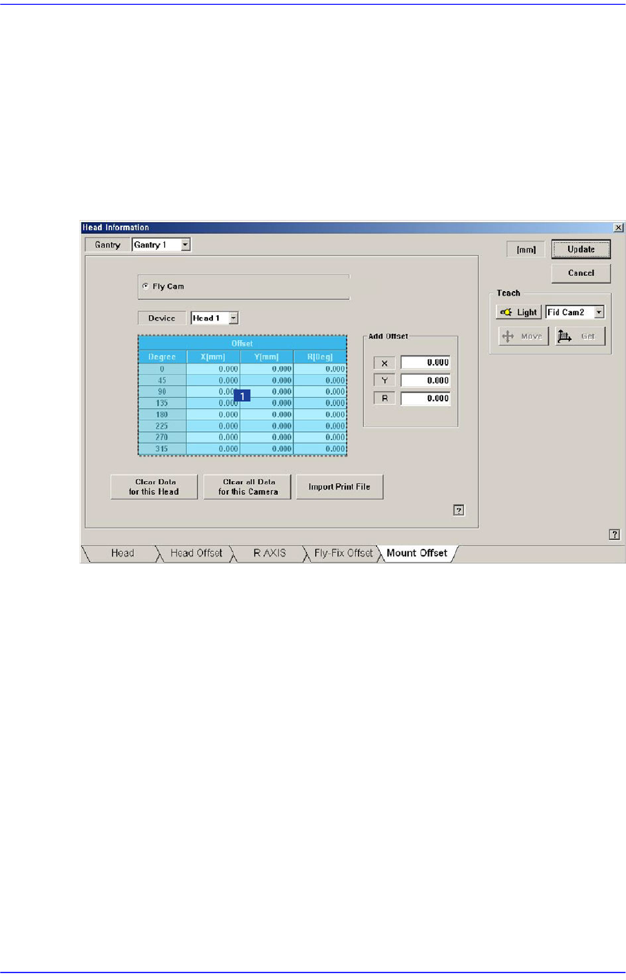
14.1.5. <Mount Offset> tab dialog
Sets the placement offset for each head.
Figure14.5 “Mount Offset” tab dialog
1: Grid group
<Fly Cam, Fix 1 Cam..> option button area
Sets the placement offset for each camera.
<Device> combo box
Sets the placement offset for each head.
<Grid> group
Sets the placement offset by degree at 45 degree interval.
<Degree> column
<Offset-X, Y, R> column
Sets the placement offset of X, Y and R.
<Clear data for this Head> button
Deletes placement offset data of the selected head.
<Clear all data for this Camera> button

14-9
Machine Calibration
Able to delete the placement offset data of all the heads corresponding to the selected
camera.
<Import Print File> button
Selecting the created Report Viewer Text file by clicking this button will apply the
offset extracted from the CPK Report Viewer to the placement offset of the current
machine.
<Add Offset> group
It is possible to apply X, Y and R placement offsets collectively to all heads.
This function is used at the factory. Users must not apply the offsets at their own
discretion.
<Update> button
Transmits the change data to the equipment and closes the dialog box.
<Cancel> button
Ignores the change data and closes the dialog box.