DECAN_S2_Admin(Eng_Ver4.5).pdf - 第233页
7-68 Advanced Chip Shooter DECAN S2 Admi nistra t or’s Guide <T est> button T ests component recognit ion by using the set align data. Please refer to “Comm o n Align Dat a” for more information. <Make Image…
7-67
Part Registration
or white when checking a bad mark.
The value can be adjusted by entering a numerical value in the edit box.
Check the <Auto> check box to automatically set up the <Threshold>
value.
<Size X> edit box
Displays the area size in the X direction.
<Size Y> edit box
Displays the area size in the Y direction.
<Pos X> edit box
Displays the X coordinate of the area center..
<Pos Y> edit box
Displays the Y coordinate of the area center.
<Rotation> combo box
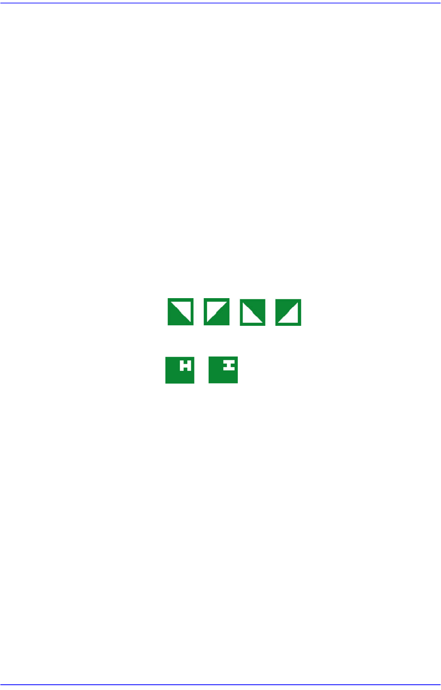
Selects the rotating angle of the direction mark. The rotation angle can be
selected according to the direction mark type as follows:
Triangle:
Circle: The angle cannot be selected.
H Mark:
<Polarity> combo box
Select the color of fiducial mark. Available colors are as follows.
- White: the mark looks lighter than the surroundings.
- Black: the mark looks darker than the surroundings.
<Outline> button
Shows the image seen through the Vision in real display to which threshold is
not applied, or in the image (Binary) to which threshold is applied as
recognized by MMI.
<OK> button
Saves the align data and closes the dialog box.
<Cancel> button
Closes the dialog box without saving the align data.
<Move> button
Used for parts recognition test by manually picking up parts. Please refer to “Common
Align Data” for more information.

7-68
Advanced Chip Shooter DECAN S2 Administrator’s Guide
<Test> button
Tests component recognition by using the set align data. Please refer to “Common
Align Data” for more information.
<Make Image> button
Displays the component shape recognized by the MMI through the SM Vision window
by assembling the split images after performing split recognition of the component.
<Image Capture> button
Helps to specify the optimum lighting value. The lighting is gradually changed
automatically and the images are saved. The user can check the best image and
identify the optimum lighting value. Please refer to “Common Align Data” for more
information.
7-69
Part Registration
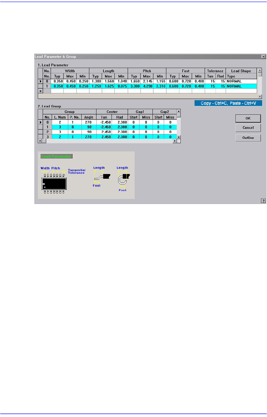
7.1.4.1. Lead Parameter
Sets the lead Parameter and lead group of the lead component.
Figure7.25 Screen showing “Lead Parameter” setting in the dialog box for “User IC Lead
Parameter & Group “
<Lead Parameter> group
Set the lead parameter.
<No.> column
Displays the lead parameter number. Possible range is 0 –7.
<Width Type> column
Set the lead width.
<Width Max> column
Input the maximum allowable lead width. (Input value = Lead Width + Allowable
Error). That is, even though the recognized lead is a maximum of 1.2mm when the
actual lead width is 1mm, if this recognized value is allowed, the maximum
allowable lead width will be 1.2mm
<Width Min> column
Input the minimum allowable lead width. (Input value = Lead Width - Allowable
Error). That is, even though the recognized lead is a maximum of 0.8mm when the
actual lead width is 1mm, if this recognized value is allowed, the maximum
allowable lead width will be 0.8mm
<Length Type> column
Set the lead length.