DECAN_S2_Admin(Eng_Ver4.5).pdf - 第444页
14-75 Machine Calibration 7. The message “Calib r ation is Prepared. T o Calibrate, Click [Ne x t]” appears. At this time, At this time select the ‘Fly1 Cam‘ in the <T arge t Camera> combo bo x and, click the <L…
14-74
Advanced Chip Shooter DECAN S2 Administrator’s Guide
If calibration is performed without selecting either the <Automatic> check box or
<Manual> check box, the nozzle is changed automatically for the currently selected
nozzle. Click the <Next> button to move onto the next step.
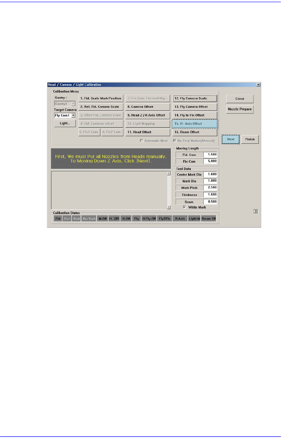
3. If the <15. R-Axis Offset> button is selected, the message “First, We must Put all
Nozzles From Heads on Manually. To Move down Z Axis, Click [Next]” appears.
Click the <Next> button to move down the Z axis of the head in order to manually
move all nozzles inserted in the nozzle-holder of the head.
4. Then, after the head assembly moves to the home position on the machine, move all Z
axes down. At this time, remove all inserted nozzles manually.
5. Then the message “Next Attach the Calibration Tool to Head 1. Click [Next] for
Moving Down Head. After Moving, Attach the Tool to Head Manually” appears.
Click the <Next> button after inserting the CN400 nozzle in the nozzle-holder of Head
#1 manually.
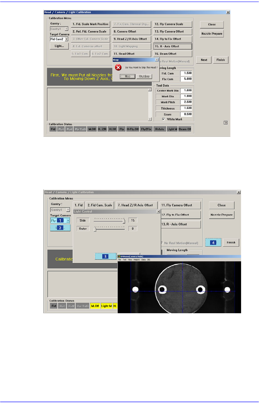
6. The message “Z Axis moving down…. Please Wait for a Moment.” appears, and the
dialog box asking whether to skip the calibration of Head1 is displayed. Click “Yes
(Y)” to skip or click “No (N)” to proceed with the calibration. And then click the
<Next> button.
14-75
Machine Calibration
7. The message “Calibration is Prepared. To Calibrate, Click [Next]” appears.
At this time, At this time select the ‘Fly1 Cam‘ in the <Target Camera> combo box
and, click the <Light…> button and adjust the brightness of the light in the ‘Light
Control’ dialog box so that the fiducial mark on the calibration tool that is seen in the
‘SMVision’ window can be seen clearly. Then click the <Next> button.
8. Recognize the 2 fiducial marks on the bottom surface of the calibration tool by using
the fly camera while rotating the head from -360 degrees to 360 degrees at 5 degree
intervals.
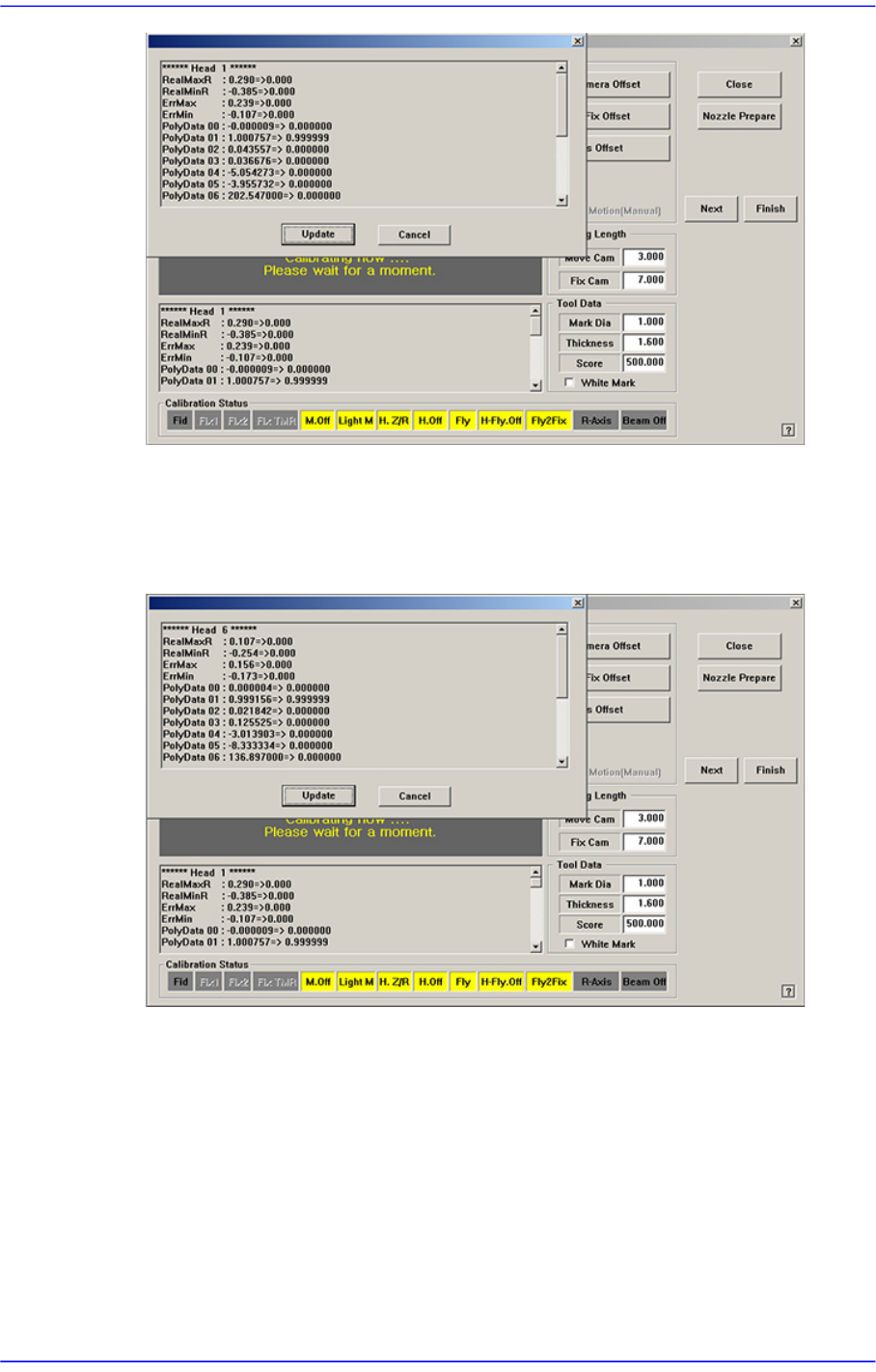
9. The calibration is performed automatically. If it is completed, the calibration result is
displayed as shown in the following figure.
14-76
Advanced Chip Shooter DECAN S2 Administrator’s Guide
10. .For Head #2 ~ Head #10, perform calibration in the same manner as it was performed
for Head #1.
11. .If the calibration procedure is completed for all heads normally, the result is displayed
as shown in the following figure.
12. .Select Gantry 2 in the <Gantry> combo box and perform calibration in the same
manner as has been done for Gantry 1.
The measurement result can be confirmed in the R Axis dialog box.