DECAN_S2_Admin(Eng_Ver4.5).pdf - 第504页
15-53 System Setup [Auto Apply Pick Up He ight = Use] [Auto Apply Pick Up He ight = Not Use] <Update> button T ransmits the change data to the equipment a nd closes the dialog box.
15-52
Advanced Chip Shooter DECAN S2 Administrator’s Guide
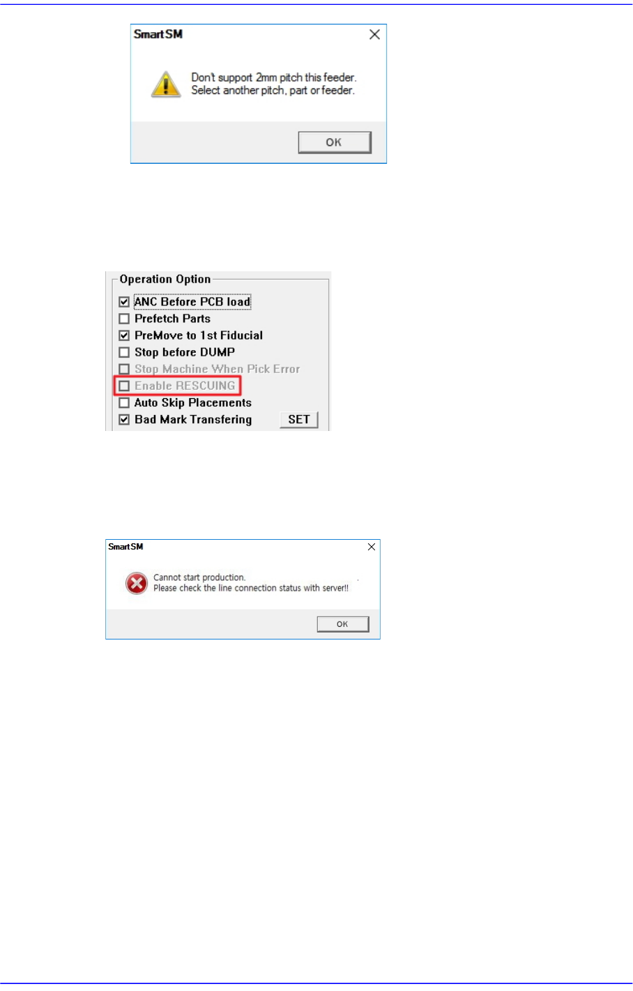
<Use RESCUING> check box
When this check box is ticked, the <Enable RESCUING> check box is activated in the
<Operation Option> area of the “Product” menu. For details on this function, refer to
“13.1.2. Option Setting”.
<PNP Connection Check> check box
Checks whether the machine and PNP are connected before starting production.
Starting production with the machine not connected to the PNP will display an error
message.
<Use Pickup Offset Sync> check box
This is selected when applying the feed angle (R) and mounting angle (Part R) of the
stick or tray feeder to the parts data registered in the feeder. When this check box is
ticked, each time the PCB file is opened, the feed angle and mounting angle of the part
are changed to the feeder data.
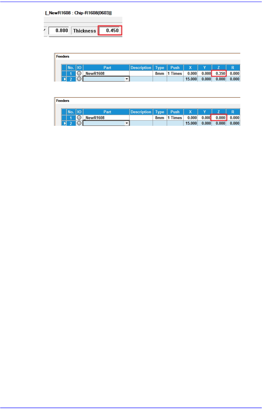
<Auto Apply Pick Up Height> combo box
When this check box is ticked, the pickup height of the part is automatically reflected
to the feeder Z value, but only for feeders whose reel type is Paper. (Pickup height of
the part: Thickness of the part - 0.1mm)
When changing the model, it takes a long time to set the pickup height of the part
when the number of tape feeders is large. At this time, you can shorten the model
change time by using this function.
[e.g.: Chip parts with a thickness of 0.450]
15-53
System Setup
[Auto Apply Pick Up Height = Use]
[Auto Apply Pick Up Height = Not Use]
<Update> button
Transmits the change data to the equipment and closes the dialog box.
15-54
Advanced Chip Shooter DECAN S2 Administrator’s Guide
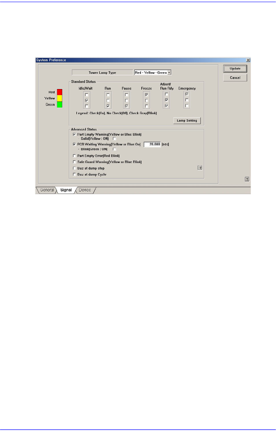
15.5.2. <Signal> tab dialog
Set the status of the signal light. When this button is selected, the following screen is
displayed.
Figure15.18 “Signal” tab dialog
<Tower Lamp Type> combo box
Select the signal tower type. Available types are as follows.
Red –Yellow –Green: When the signal light consists of “Red –Yellow –Green”.
Red –Blue –Green: When the signal light consists of “Red –Blue –Green”.
<Standard Status> group
Set the status of the signal light corresponding to the equipment status.
For example, if you want to turn on the “Yellow” lamp of the signal tower in the idle/
wait status, check the corresponding “Yellow” lamp check box among the 3 check
boxes under the Idle/Wait.
The status and meanings of the check boxes are as follows.
Checked: Turns on the corresponding lamp.
Not checked: Turns off the corresponding lamp.
Checked in gray: Flickers the corresponding lamp.
<Lamp Setting> button
The user can perform setup concerning the error by which the red lamp of the
signal light is turned on by default so that the yellow lamp is turned on selectively
according to the error type. Clicking this button will display the following dialog
box.